Channeling creativity when working on your hot rod is one of the main ways to infuse newfound personality into its design and construction, separating it from the rest. Over several issues, the team at the Rolling Bones Hot Rod Shop in Greenfield Center, New York, completed major fabrication elements on Dick DeLuna’s ’34 Ford coupe. They did so by lowering its cowl line, eliminating its lower frame point, and updating its front subrail assembly, thus adding plenty of exciting attitude to its overall appearance.
Focusing on the final stage of the metamorphosis, team member Keith Cornell prepared the coupe for a thorough reworking of its front framerails. Examining the ’rails, the factory upward sweep was the first issue to be addressed since in order to achieve the new proportions the ’rail would need to be flattened to flow correctly with the recently dropped cowl line and reworked lower frame point.
 When we last left off, the bottom framerail point had been reworked, a new subrail assembly had been fabricated, and the cowl and rocker extensions had been installed, giving a newfound sleekness to the front of the coupe.
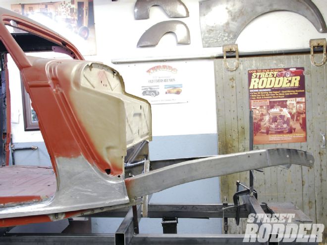
To determine the amount of flattening out required for the ’rail, a section of angle iron was first clamped to its top from the cowl forward using a pair of C-clamp Vise Grips. Following the line of the angle iron, it was apparent that a number of pie-cuts would be needed to flatten it out. To identify the first cut required, a measurement of 11 inches was taken from the front of the cowl to the point atop the ’rail where it began to drop from the angle iron. Using a square and black marker, Cornell marked the top and side of the framerail to prepare it for the initial 90-degree cut.
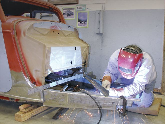
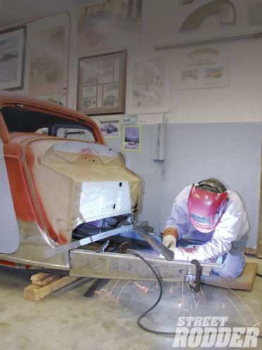
It’s important to ensure that the framerail is properly supported up front prior to cutting. While wearing protective glasses and work gloves, he used a Hypertherm Powermax 30 plasma cutter to make the incisions followed by a small air-driven grinder topped with a 40-grit disc to deburr and clean up the area. With the framerail slightly bent open for access, it was determined that a 1/4-inch pie-cut would be needed. Using a square and black marker, the cut was marked to both the side and top. A smart tip from Cornell was to use a small section of 1/8-inch angle iron clamped to the ’rail to act as a perfect straightedge when making the required cuts. He followed with a plasma cutter to trim and disc grinder to clean up the area. Once completed, the ’rail was bent back in place and the angle iron was clamped back atop the ’rail starting at the cowl.
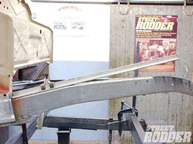 To establish the new proportions of the front ’rail, the factory sweep needs to be flattened out. To do this, a section of angle iron was clamped in place from the base of the cowl forward.
A measurement was then taken from the initial cut forward illustrating 3 inches had been gained in flattening out the ’rail. To keep everything secure as the job proceeded, Cornell tacked the ’rail back together using a Millermatic MIG welder. Note that all final welding will be done with a TIG welder for additional strength. After using a square to mark the cut to the framerail top and side at 3 inches from the last cut, the section was opened using the plasma cutter. After grinding the area smooth, it was determined a slight pie-cut of 3/16 inch was required for the second trimming. With the ’rail supported and bent open, Cornell completed the removal using a plasma cutter. Once the area was ground smooth it was tacked in place using a MIG welder. The section of angle iron was clamped in place atop the ’rail for the final time illustrating 5 inches were gained from the second pie-cut. To complete the flattening of the framerail, the cut to the top and side of the framerail (at 5 inches from the second cut) were marked with a square and the incision was completed with the plasma cutter. Cornell studied the amount of the final pie-cut and determined that 3/16 inch would do the trick. With the area ground clean and ’rail bent open he used a square to mark the trimming required and zipped the amount from the ’rail using a plasma cutter. Once deburred and smooth, the area was supported and tacked in place. The final welding was then completed using a TIG welder and all welds were ground to a mirror-like finish using a grinder topped with an 80-grit disc. One important note Cornell advised us of was that not all framerails are equal so the pie-cut amounts could vary slightly from side to side.
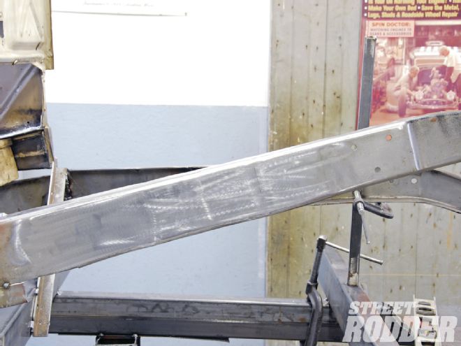 Once all the TIG welding was completed, the finished framerail looked factory fresh.
With the flattening to the framerail completed, it was time to focus on the final stage of the framerail reworking. Using a square, a cut line was established from the front of the cowl across the top, bottom, and side of the framerail to prepare it for removal. The cut line was then matched with masking tape once the body was moved back atop the chassis. Using a plasma cutter (and assisted by fellow team member Ken Schmidt) the framerail was cut off the chassis. The area was then deburred and cleaned up using a 40-grit disc. In order for the framerail to better flow with the new lowered cowl line, a 5/8-inch reverse pie-cut was established on the cowl end of the framerail using a square and black marker. Cornell used a plasma cutter to remove the section followed by a 40-grit disc to smooth everything out.
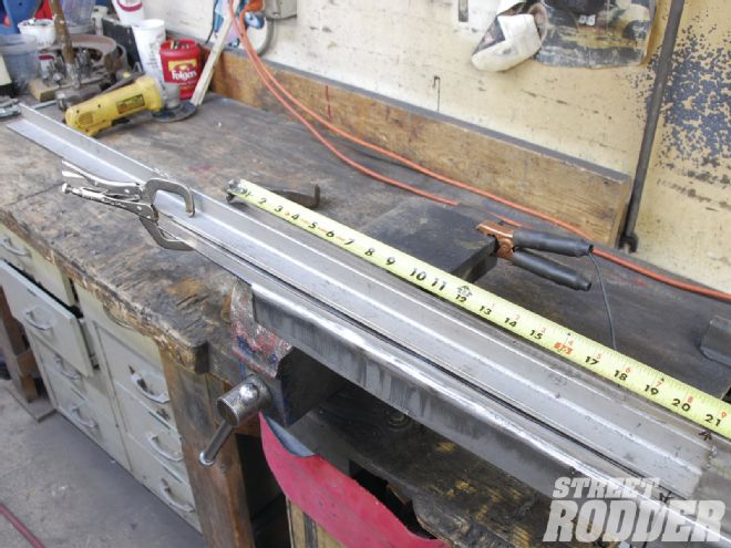 With the frame section clamped to a bench vise, a measurement of 21-1/2 inches was made from the cowl end forward. A cut was marked for a gradual wedge opening to follow along the bottom of the ’rail.
To complete the modifications, the framerail section was then secured to a bench vise. In order to gracefully blend the reversed frame point section on the bottom of the framerail, a measurement of 21-1/2 inches was marked from the cowl side forward along the bottom of the section. The framerail width of 4 inches needed to be opened up to 5 inches at the cowl end to accomplish this. Cornell first used the plasma cutter to open up a gradual wedge in the bottom of the framerail. He then followed by confirming the measurements of the wedge over the 21-1/2-inch span and then removed the balance of the lower wedge from the ’rail with the plasma cutter. A new lower framerail section was then fabricated using a section of 1/8-inch rectangular steel tubing. With the new section clamped into place, Cornell TIG-welded it to the framerail. The completed unit was then TIG-welded to the chassis wrapping up the updates. With all welds ground smooth using an air-driven grinder topped with an 80-grit disc, the completed job looked factory fresh. Once the car was back on the ground and mocked up with wheels and tires it was easy to see the changes had updated the overall personality of the car in a major way by adding plenty of speed and style to the mix by lowering the cowl line and tweaking the framerails.
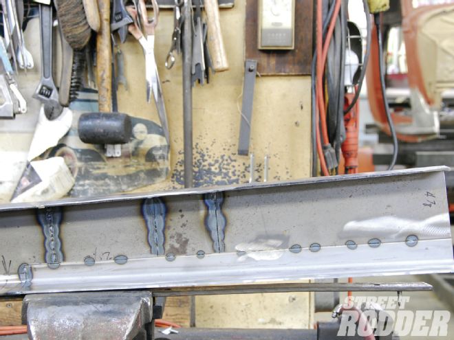 This close-up lets you see the perfect melding of the new section to the bottom of the ’rail.