One of the most significant elements of any hot rod build is without question a well-designed and thoroughly thought out perimeter chassis. While there are tried and true formulas regarding a well-balanced chassis for either traditional or contemporary-based build styles, many times a shop will infuse some unique details to separate their bones from the rest.
We've closely followed the build-up of a Deuce five-window at the Rolling Bones Hot Rod Shop in Greenfield Center, New York, over the past few months, and with the chop, panel replacement, and lead work complete, it's time to focus on how the team creates one of their signature perimeter chassis.
Keith Cornell of Rolling Bones began the project with a pair of American Stamping Corporation Deuce framerails. To begin, Keith prepared the 'rails for mounting to a frame jig by drilling four 1/2-inch mounting holes where the steering sector shaft and rear fender mounts would be on an original Deuce chassis. Once the 'rails were properly anchored, Keith followed using a carpenter's level to ensure that everything was properly balanced before proceeding. American Stamping's 'rails are delivered with all of the top factory mounting holes pre-drilled as well as those for the spreader bars on the side. Keith's first order of business was to cut a good amount of 1/2-inch steel sheet stock that would be used for extra reinforcement mounting bungs for the firewall and body areas. Using his MIG welder and adequate safety gear, Keith secured the bungs into place, to be drilled and tapped later to anchor the firewall. To give the new 'rails that old-time feel, Keith then C-clamped a steel template to the inside front area of the frame to duplicate all of the factory mounting holes. A quick shot of paint to secure the layout followed by a 1/2-inch drill had the 'rails looking like Henry's originals in a snap.
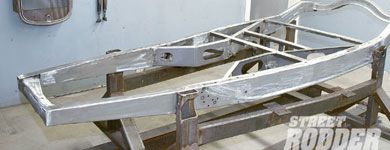
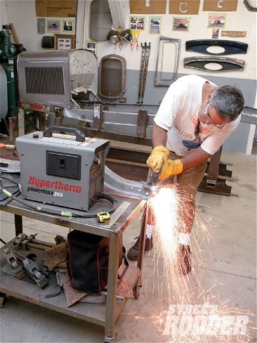
One of the more recognizable components of a Rolling Bones-built hot rod is how perfectly the hood sides line up with the tops of the chassis 'rails. To achieve this look Keith prepared the front of the 'rails to be pinched by first setting his marks using a square and a black marker based on a pre-determined point (roughly 37 3/4 inches from the front tip of the new 'rail) on their jig for where the initial cuts should be made. Once the upper and lower portions of the 'rails were marked, Keith used his Powermax Hypertherm 350 plasma cutter to remove a 1-inch wedge from both planes. This gave the chassis a 2-inch overall pinch and will allow the hood sides to flow gracefully with the 'rails. Another key Rolling Bones component to the front area of the 'rails involves determining just the right amount of bob that would be needed to achieve their look. For this particular car, Keith determined that since he plans for it to have a 109 1/2-inch wheelbase and a hood which will be 2 inches longer than stock, that 12 inches needed to be removed from the front of the framerails. Once the cut marks were laid out, Keith again used his plasma cutter to seal the deal. With the pinch and bob completed, Keith secured another jig to the front of the chassis to get everything perfectly square and lined up for the final MIG welding to be completed.
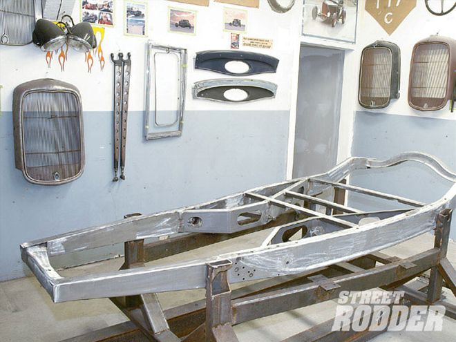
To tie the wishbones together up front Keith used a new Model A crossmember from Brookville Roadster which needed to be cut down to fit the application. After locating the center of the crossmember, Keith measured from the center point outwards to the inner portion of the 'rail to determine the amount to be trimmed. For this application, a graduated trim from 1 7/8 inches from front to 1 1/2 inches rearward made for the perfect fit which Keith trimmed with his plasma cutter. In order to achieve the proper caster layback of the crossmember, Keith used an angle finder to locate the stock 3-degrees caster and determine the trimming needed to achieve the needed 10-degree layback. Using a small disc grinder, Keith completed the final notch trimming that got everything dialed in. With the front crossmember now situated, Keith used a 3/8-inch drill bit to cut through the reinforcement bungs for the firewall and then followed with a 3/8-inch coarse tap on the correct factory angle to ready the chassis for the test installation of the firewall. With the firewall secured into place, Keith proceeded by installing the grille shell, complete Rootlieb hood, and front axle to be sure that everything was proportionately perfect. Even though we will be covering the development of the front and rear suspension in upcoming articles, it was necessary to locate the 2-inch longer-than-stock split wishbones during the perimeter chassis build-up. The chassis mounting location of the split bones would need to be approximate, and Keith used an angle finder to locate the exact spot on the side of the framerail at 10 degrees of caster. Once the location was marked, Keith used an air-driven drill with a 1/18-inch hole saw attached to make the opening for a reinforcement bung to be MIG welded from the inner 'rail. Once the bung was in place, Keith then C-clamped the American Stamping chassis boxing plates into place and marked them to be cut with a 2 1/2-inch hole saw to accommodate an inner steel sleeve that would be welded in for additional strength. While the boxing plates were in place, Keith also made any markings for trimming that would be required prior to the final MIG welding of the plates to the framerails.
As Keith moved to the back of the chassis, a stock original Model A rear crossmember was placed atop the rear 'rails to establish the trimming needed for the application. With the rear spreader bar in place to secure the rear width of the chassis, it was determined that 1 3/8 inches would need to be trimmed from each side with a plasma cutter. The location of the rear crossmember is of the utmost importance for rear wheel placement, and Keith tells us that if you miss this, you'd better call it quits, since the car will never look right. To get it perfect, Keith secured the crossmember 1 1/4 inches ahead of the rear most body bolt. Keith then temporarily bolted the crossmember into place and used an angle finder to locate 0 degrees. Once 0 degrees was found, he fabricated a steel wedge that was welded into place on the inner upper portion of the 'rail to secure the proper angle. Then it was time to "bob" the rear of the 'rails for additional modifications as they will later be reattached to the chassis. The final tie-in of the perimeter chassis came when Keith clamped the Brookville Roadster '34 Ford-style X-member into place to secure its approximate location before commencing any TIG welding on the unit. There were a few add-ons to the X-member, including additional 1x2x1/8-inch rectangular steel supports for added strength and custom-fabbed rear ladder bar mounts, which will be covered in detail in an upcoming rear suspension story. With all of the final MIG and TIG welding completed, the perimeter chassis was a glistening masterpiece that will be the base for this wicked Deuce. Stay tuned, 'cuz we're about to reveal a number of cool Rolling Bones suspension secrets.