 Whether you do the work yourself or have a professional shop do it for you, a proper alignment is critical to improved handling and better tire wear.
Car crafting is all about resurrecting an older car and putting the tune to it. Some cars have a decent foundation from which to start the process, while others0 need a little more help. The first-two-generation Mustangs from '64 through the early '70s used stamped-steel shock towers held together by a few factory tack welds. We doubt the Ford engineers at the time even considered that any of those cars would still be around as drivers 40-odd years later, but here we are.
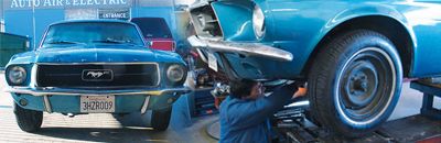
Enter Car Craft's grandma-gnashed '67 Mustang that we plan to turn into a canyon carver. While we fantasized about chicks digging us behind the wheel of a Trans Am/Jerry Titus-look-alike boulevard scorcher, the reality was the front suspension needed more than a couple of new parts. It was going to take something just short of divine intervention to resuscitate this bruised cruiser. Former CC staffer Terry McGean and fellow Mustang and Fords staffer Miles Cook turned us on to a guy who could straighten our act out and help us get it back on the road. It would take some serious hydraulic ram work and even some welding before we could get cozy with the alignment gods, but it all came together rather easily once we learned the secret to early Mustang front-suspension success.
Bent But Not Broken
Our first thought was to bolt a bunch of new Global West Suspension parts on our little ponycar and be done with it. But after a quick lesson in Mustang front-suspension sheetmetal fatigue, we learned we needed help from someone with chassis-tweaking experience, so we delivered our notchback Mustang to chassis man Marlon Mitchell at Marlo's Frame & Alignment in Chatsworth, California.
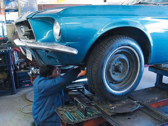
It was clear from a quick visual inspection that our Mustang was suffering from a classic case of SSTS (separated shock-tower syndrome). This is where the upper control arm shock-tower plates that are spot-welded to the rest of the sheetmetal front clip have started to pull apart. According to Marlon, all the early Mustangs do this-some are just more bent than others. In radical cases, the sheetmetal will actually rip apart. All this is the result of normal, everyday driving when impact loads from potholes tend to gradually bend the thin tin that holds this car together. When this happens, the separated plate pulls the upper control arm inboard, creating increasingly more negative camber. Our Mustang had pulled apart very badly on the left (driver) side, so that's where Marlon started his repair.
You might think all you have to do is wield a big hammer and beat that mounting plate back in place. But this is not the best plan. It's not even a good plan. Instead, Marlon dragged out a hydraulic ram that he uses to force the top of the spindle to bend the sheetmetal back into its original place. We watched him force the upper part of the spindle with the ram, and the amount the spindle moved was shocking-at least 3/4 to 1 inch before both sides of the shock-tower panel were properly repositioned.
Once the shock tower is forced back in its proper position with the ram holding it in place, Marlon MIG-welded the support and the shock-tower sheetmetal together at the seam. This radically improves the strength of the design over the original factory spot-welds. Once Marlon had welded all four seams on both sides, the front alignment gained what looked like 3 to 5 degrees of positive camber. That's how much the sheetmetal had deformed over the years. Now we were ready to swap in all the trick new Global West Suspension pieces. Since this step is also something we will detail, we're going to skip over that portion, saving it for next month's installment.
Alignment Basics
Before we get into the wrench-turning part of the story, we should review exactly what this talk about caster, camber, and toe is all about. Let's start with camber. If you look at a car directly from the front, camber is defined as the inward (negative) or outward (positive) tilt of the top of the spindle. This is a high tire-wear angle and also has a dramatic effect on vehicle handling.
Looking at the car from the side, caster is the forward or rearward tilt of the top of the spindle. If we're looking at the left or driver front tire directly from the side, when the top of the tire tilts back toward the rear of the car, that's called positive caster. This is an angle that promotes high-speed stability and good handling. If the top of the tire is tilted forward, that's called negative caster. This angle reduces steering effort but hurts high-speed stability and should be avoided. Also note that ride height will have a big impact on both of these angles.
Toe is another critical tire-wearing angle and can best be envisioned if you imagine looking straight down on the front tires while standing in front of the car. Toe-in is where the leading edges of the two front tires are closer together than the trailing edges. Toe-out is the opposite, where the leading edges are farther apart than the trailing edges. As you can imagine, excessive amounts of either toe-in or toe-out are not good. Most musclecars generally prefer a small amount of toe-in, along the level of 1 1/32 inch per side for a total of around 1/16 inch.
 This is the early Mustang camber-adjustment plate from Global West. Note the three different offset holes that adjust the camber. This design will not move, but it requires more effort to adjust than the factory eccentric.
Alignment Angles
Before you get started with adjusting these angles, it's important to make sure all the front-suspension components are in good condition. Before performing the alignment on our Mustang, we converted the Mustang over to a complete Global West Suspension system, but we'll save that how-to for a later story. This ensured that all the front-suspension components were either new or rebuilt and ready for some street fun.
The early Mustang front suspension is a bit different from the typical unequal-length upper and lower control arm suspension where the coil spring is located between the upper and lower arms. The Mustang suspension places the coil spring on top of the upper control arm with a strut rod placed at an angle to the lower control arm that makes its position adjustable for caster.
Camber is the first adjustment Marlon made to the Mustang. Ford uses a round eccentric for the inner pivot point of the lower control arm that is held in place by a single bolt. Loosening the bolt and turning the eccentric moves the lower control arm in (creating positive camber) or out (negative camber)-remember, this is the lower control arm we're talking about. Global West makes a bolt-in eccentric with three offset holes that lock in the camber setting, but it requires you to remove the eccentric every time you change the camber alignment. On GM musclecars, creating negative camber is as simple as adding shims on both studs of the upper control arm. Adding positive camber is even easier, since all you have to do is remove as many shims as necessary.
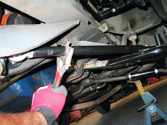 Changing caster on the Mustang involves merely changing the length of the strut rod. Decreasing its length adds positive caster by tilting the top of the spindle rearward.
Caster adjustment is also simple on these early Fords. Lengthening the strut rod moves the lower control arm backward, creating negative caster, while shortening the strut length pulls the lower control arm forward, creating positive caster. On GM musclecars, caster is a little more complicated. Adding positive caster involves adding shims only to the rear stud on the upper control arm, while adding shims to the front stud will increase negative caster. This effectively moves the upper portion of the spindle either forward (negative caster) or rearward (positive caster).
Toe changes are also easy, since adjusting the tie-rod turnbuckles will change the length of the steering assembly. Increasing the length of the steering rods will push the tie rods out. Always make the same changes to both sides of the tie-rod ends so each changes the same relative to the centerline of the car. Another variable is whether the car is a front- or rear-steer car. A front-steer car places the steering linkage in front of the true axle centerline, while a rear-steer car places the linkage behind the centerline. Lengthening the steering linkage on a front-steer car will create toe-out, while doing the same on a rear-steer car will create toe-in. Simple, no?
Home Alignment Tricks
If you're one of those guys who prefer to do the work yourself, for a small investment, you can do the same job as most alignment shops and be able to do it at your leisure. Many outlets, such as Longacre, Smart Racing, and most circle-track shops sell alignment tools that will allow you to do it yourself. A new magnetic-bubble alignment gauge costs less than $200. Always adjust the camber first, then caster, and set the toe last. This is because camber will affect caster, and both of these will directly affect toe.
After adjusting toe in your garage, you must always roll the car backward and then forward roughly half a car length before measuring. This places the proper force on the tie-rod ends. If you do not roll the car, the toe will be incorrect. The other important consideration is a level or near-level work surface. If your garage floor is not level side-to-side, this can introduce errors into your measurements.
Measuring camber is easy for most cars; all you have to do is place the gauge on the hub of the front tire and read the numbers. For caster, the big boys use turn plates to turn the tire 20 degrees in and zero the gauge and then turn the tire 20 degrees out and read the change in camber. This change in camber creates the caster angle. If you don't have turn plates, you can pin two pieces of 1/8- or 3/16-inch flat aluminum plate together, and put chassis grease in between to help them spin. Then use a protractor to mark 20-degree turn-in and turn-out points on the plates. It sounds cheesy, but it works. A better alternative is to buy a pair of used, cast-iron turn plates at a swap meet. We bought ours for less than $30, so the stuff is out there. Try it. You might have fun with it!
Front-End Alignment Specs