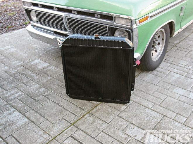
 <strong>1.</strong> Our Hot Rod Hauler presents some challenges when it comes to cooling—it has lots of horsepower and is often heavily loaded. That’s why we opted for a Tripleflow copper/brass cooler from U.S. Radiator.
We all know hot trucks are cool. On the other hand, trucks that run hot aren’t cool. There’s nothing worse than steam coming out from under the hood of your prized pickup while boiling coolant pours onto the ground. Overheating can be an inconvenience or a catastrophe depending on when and where, and to what degree (no pun intended) overheating takes place. But the fact is, with a properly designed cooling system, overheating should not be a problem.
When it comes to engine cooling issues we routinely turn to Don Armstrong of U.S. Radiator. The company has been in business for over 50 years and Don has been there for more than 40 of them. He began as a delivery driver, worked in every facet of the operation, and now owns the place. Today, under his leadership, the company produces over 400 different radiators.
Don has years of experience and does constant research to stay up with the latest cooling system technology, and as he explains it, the core design and not material had the greatest effect on temperature drop. Here’s what he has to say on the subject:
“While all radiator cores might look the same, they perform vastly different based on tube spacing and fins per inch. The heat transfer points of a radiator are where temperature is actually allowed to leave the radiator and that occurs where the fins are bonded to the tubes. The more transfer points a radiator has, the greater the temperature drop will be between the inlet and outlet.
“For comparison, a ’60s-style core typically had tubes spaced ½-inch apart; that is ½-inch of fin between the tubes. By going from a two-row radiator to a four-row core design we were able to double the heat transfer points which resulted in a 15-20-percent increase in temperature drop without changing the other variables such as air or coolant flow.
“U.S. Radiator offers four distinct core designs. The Standard that is found in most OEM-style radiators, the High Efficiency aluminum with 20-percent more heat transfer points, the High Efficiency copper/brass with 20-percent more heat transfer points, and the Optima copper/brass that uses ¼-inch tube spacing with ¼-inch fins that provides 40-percent more heat-transfer points.
“Radiator materials have created quite a bit of controversy. In the ’80s, the Japanese came out with a core design in response to the need to downsize radiators and that has become the industry standard because it was efficient enough to allow the re-introduction of aluminum (a less efficient heat-transfer material) at the O.E. level.
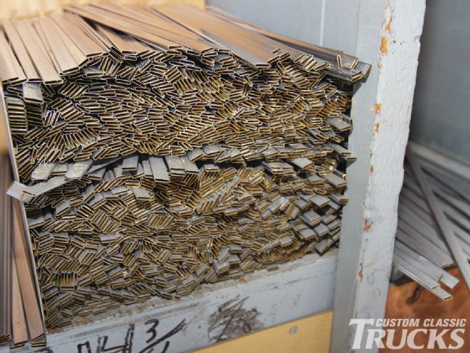 <strong>2.</strong> One of the few things U.S. Radiator doesn’t build in-house, these tubes are part of the core; they come coated with solder.
“By changing the tube spacing to 3⁄8-inch, a core design referred to as High Efficiency in the industry, more tubes or water passages and fins were allowed across the face of a core with a specific width in inches. The design was simple enough, but proved to be very efficient in that more heat transfer points created greater temperature drop inlet to outlet.
“It should be pointed out that the move to aluminum radiator construction was purely financial. The raw materials to build a radiator are purchased by the pound and a finished aluminum radiator weighs about 25-percent of a copper/brass unit (dollars per pound being almost equal at that time). The result was a huge financial savings for car companies.
“When it comes to the difference in performance between copper/brass and aluminum radiators you may find the tests by U.S. Radiator surprising. We found that temperature drops at all operating ranges were virtually the same, with a slight advantage going to the copper/brass unit. But consider this: The thermal conductivity or heat-transfer rate of copper is 92 percent versus aluminum at 49 percent.
“However, the copper fin is bonded to the tubes or water passages using lead solder which is very inefficient and slows the heat transfer rate to just slightly better than that of aluminum. This can be a disadvantage if the bonding process does not allow the copper fin to touch the brass tube and why not all copper/brass cores of similar design, but different manufactures, transfer heat equally.
“Copper/brass radiators, because of their weight and durability, have been around a long time and are easily disassembled and reassembled for cleaning purposes. Not the case with aluminum unless speaking of the O.E. version that comes with crimp-mounted plastic tanks. As a result, the life expectancy of the aftermarket aluminum radiators will be far less than that of copper/brass.”
The Tripleflow Option
Something relatively new in radiator design from U.S. Radiator is the Triplepass core. As the name implies, coolant flows through the core more than once. In a standard single-pass radiator the coolant enters one tank, travels through the core, and drops in temperature based on that particular core’s ability to reduce temperature (usually about 30 degrees).
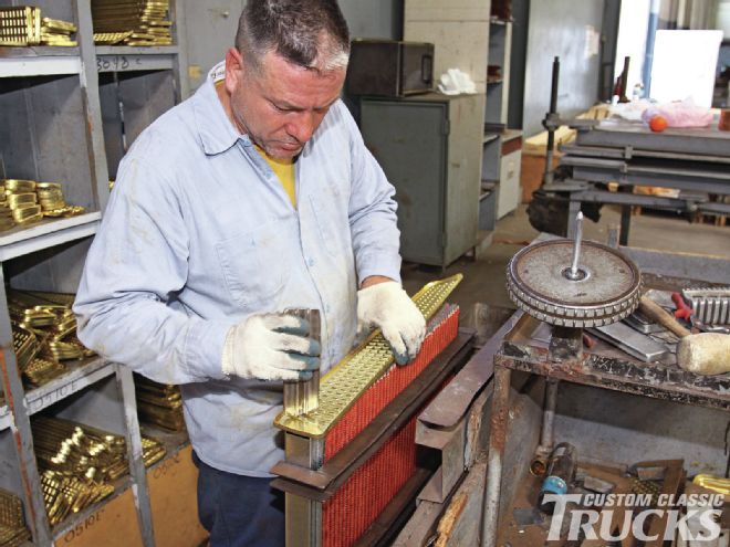
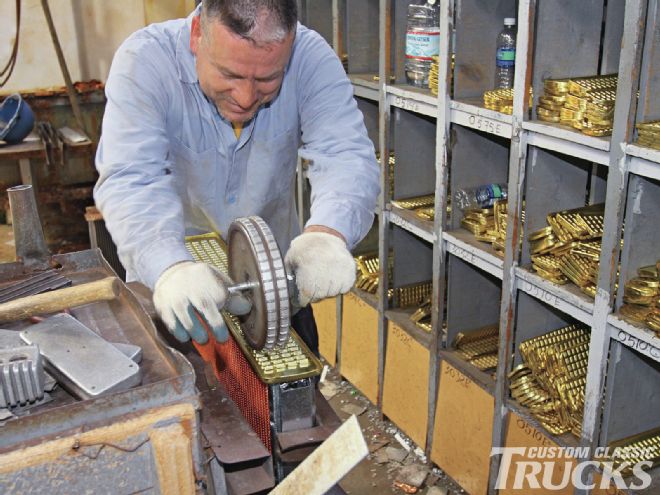
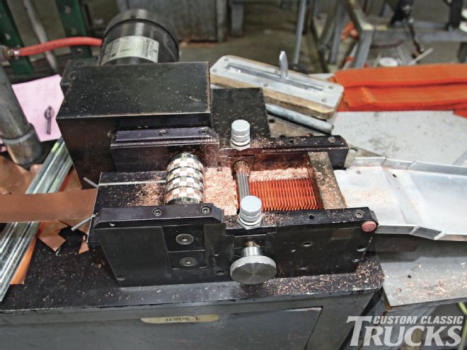 <strong>3.</strong> This machine turns sheets of copper into the fins that will be placed between the tubes. The fins actually have tiny louvers to increase efficiency.
Once the coolant reaches the other tank it goes back to the engine at whatever temperature the core was able to reduce it to. In a triple-pass design the coolant actually travels three times as far in the airflow without changing the speed of the flow, which creates an even greater temperature drop (usually an additional 20 degrees) depending on the design of the core or heat-transfer points.
Given that our Hot Rod Hauler has a 545ci engine pumping out 542 horsepower, and is usually loaded to the gunnels and hooked to a loaded trailer, cooling is a major consideration. When we asked Don for his advice on the subject, he suggested we install an Optima core with the triple-pass option, that’s what we did.
Cooling System FAQs
Courtesy of U.S. Radiator
Q. What are the advantages/ disadvantages of copper/brass vs. aluminum radiator construction?
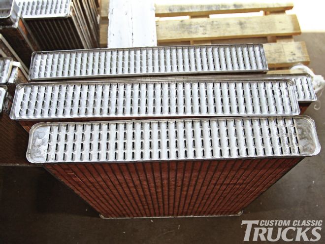
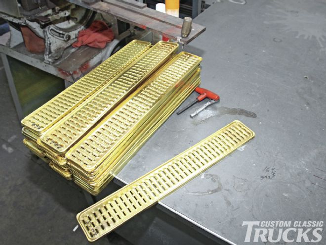 <strong>4.</strong> These are the headers that are attached to the ends of the cores; they’re stamped in-house. Note these accept three rows of tubes.
A. The thermal conductivity or heat-transfer rate of copper is 92 percent versus aluminum at 49 percent. However the copper fin is bonded to the tubes or water passages using lead solder, which is very inefficient and slows the heat transfer rate to just slightly better than that of aluminum. This can be a disadvantage if the bonding process does not allow the copper fin to touch the brass tube and why not all copper/brass cores of similar design, but different manufactures, transfer heat equally.
Copper/brass radiators, because of their weight and durability, have been around a long time and are easily disassembled and reassembled for cleaning purposes. Not the case with aluminum unless speaking of the O.E. version that comes with crimp-mounted plastic tanks. As a result the life expectancy of the aftermarket aluminum radiators will be far less than that of copper/brass.
Q. What are recommended engine-operating temperatures?
A. Most hobbyists aren’t concerned with fuel efficiency, so our recommendation would be 175-195 degrees. Higher operating temps will burn fuel more efficiently, but the increase in operating pressure and metal distortion can easily create problems over time.
Q. Do you recommend internal or external transmission coolers?
A. External transmission coolers are preferred to keep unnecessary heat out of the radiator.
Q. How does radiator core thickness effect cooling?
A. An increase in thickness over a stock application allows for greater fin bond surface and therefore greater temperature drop. When going from a two row to a four row, for example, you double the fin bond or heat-transfer points. The increase, however, isn’t a 1:1 because the transfer efficiency of the trailing rows is adversely affected by the increase in air temperature from the previous rows and the decrease in air velocity caused by the increased thickness.
Q. Do you recommend mechanical or electric fans?
A. This is an easy one. Why rely on another operating system (that being electrical) if you don’t have to? Mechanical fans turn when the motor turns. However, we highly recommend a shroud properly fitted to the fan and radiator. The only time you really depend on a fan is at idle or low speed where there is little or no air flowing through the grille. Shrouds are necessary to maximize the amount of ambient air being pulled through the grille and radiator.
For the record, proper fan and shroud alignment should be leading edge one-third in and trailing edge of the fan two-thirds out. The airflow off the back of the fan deflects at about a 45-degree angle when set this way. When the blade extends further into the shroud, the air off the back of the blade flows straight back into the block and decreases the airflow efficiency by about 15 percent.
That being said, if an electrical fan is the only way to go, then by all means place it on a shroud that covers the entire core. We often see an electric fan attached directly to the core and the only thing this does is waste the rest of the core surface when you need it the most. A 16-inch electric fan attached to a core only cools a 16-inch circular section of that core. Where space is an issue U.S. Radiator offers a ¾-inch-deep aluminum shroud that enables adequate airflow over the entire core, and when combined with a thin-line electric fan, results in a total depth of 2¾ inches.
Q. How much pressure should the cooling system be under?
A. Cooling system operating pressures are largely determined by water pump operating pressures and we prefer to keep it under 10 pounds. We all know by increasing the system pressure by 1 pound we increase the boiling point by 3 degrees, so by running a 12-pound cap our water won’t boil until it gets to 248 degrees. Trust me, an engine that wants to run at 248 degrees will open that cap up long before it gets that hot. To deliberately increase the operating pressure to increase cooling is redundant in my opinion and again only points out the need for more efficient heat transfer.
Pressures will increase in the system just after turning off the engine as the coolant absorbs existing engine heat, but can’t move through the radiator to dissipate it. The resulting increase in pressure pushes coolant past the cap and hence the need for a coolant recovery system.
Once the coolant in the idle engine starts to cool, a vacuum is created and another valve in the cap opens and prevents the radiator from collapsing a top tank, but more importantly, returns the coolant to the radiator so no outside atmosphere or air (contamination) enters the sealed system. Unfortunately most aftermarket recovery tanks are smaller than the needed capacity and that varies with cubic inches and size of the engine.
Q. How is the size of radiator determined?
A. There are formulas to determine appropriate radiator size based on engine heat output (operating BTU’s) and radiator heat-transfer rates (also stated in BTU’s). They can be found in any engineering handbook, but my recommendation to a hobbyist is to put in the most efficient radiator that fits the hole or intended application, up to a four-row copper/brass or two-row aluminum core. I think everyone knows by now that copper/brass units use ½-inch tubes while aluminum uses 1-1¼-inch tubes. That way the thermostat or lower limit control can maintain the lowest temperature you’ve determined best for all driving conditions.
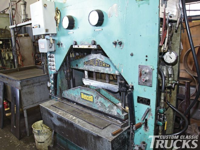
5. Tanks are formed in this press. U.S. Radiator has dies to make tanks for virtually any application.
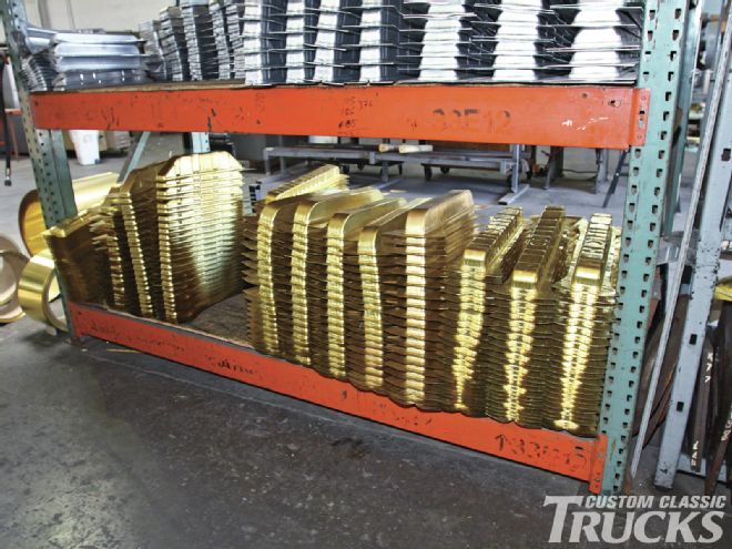
6. This is a small sample of the brass and aluminum tanks kept on hand. Note the edges have not been trimmed and the connector and cap locations will be established for the specific application.
7. The core assembly process begins with the fins and tubes in a fixture and the installation of the headers.
8. As each header is put in place a special roller is used to make sure the openings in the ends of all the tubes are uniform.
9. Assembled cores are sent on a conveyor through an oven where the solder on the tubes melts securing them to the fins.
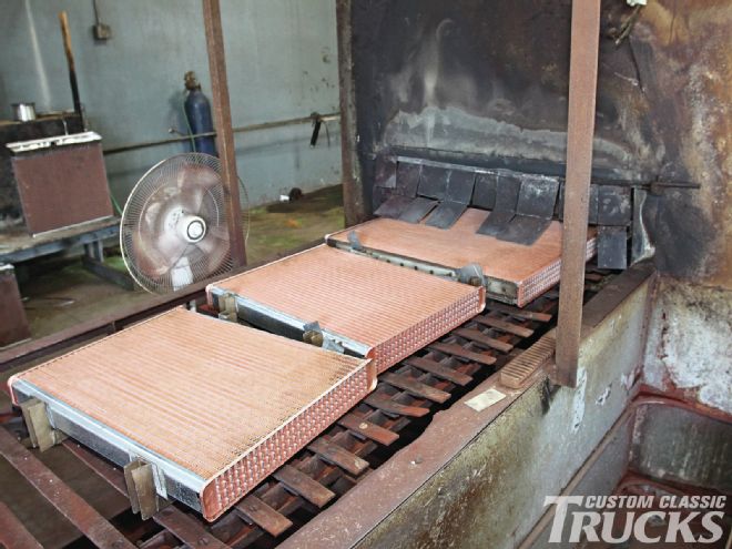
10. Out the other side of the oven come the nearly completed cores.
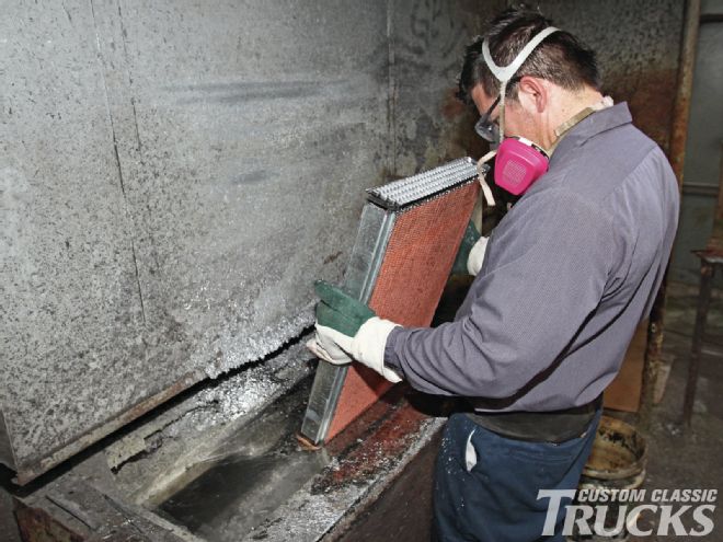
11. After the cores have cooled sufficiently the headers are dipped in solder to permanently attach the tubes.
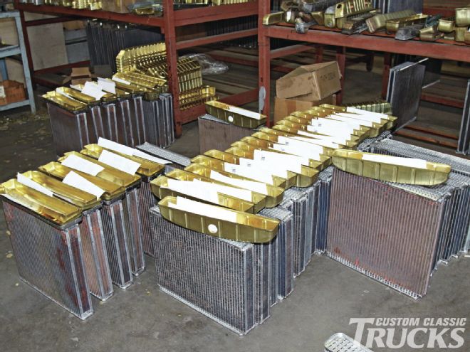
12. Here is a selection of completed cores. Note the difference in the width of and shape of the headers.
13. These cores await the installation of the side straps and tanks; then they are off to customers.
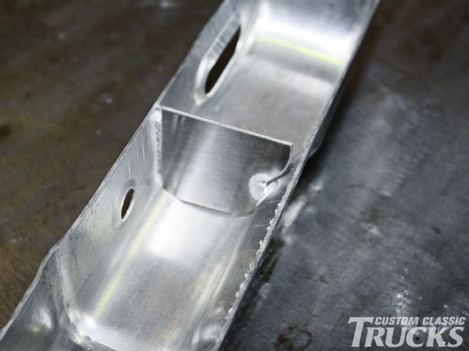
14. This is one of the baffles used in the Triplepass option (this tank is for an aluminum radiator). Baffles are strategically placed to force coolant through the core three times.