It can’t be done. You just can’t make a lot of power with cheap cast-iron heads. Certainly you can’t make 600 hp out of a 383 with them. And for sure you can’t do it without a bunch of compression. That’s just common knowledge. Well, apparently nobody told brothers Rick and Randy Ferbert, because they did all of the above.
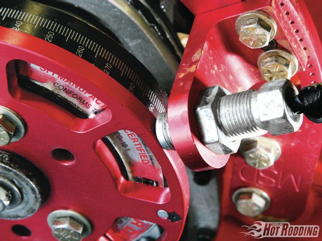
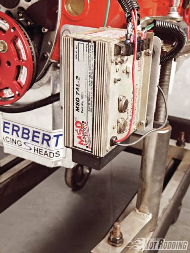 Though this was a “low compression” engine, it built a ton of cylinder pressures so the guys went to the big spark output of an MSD 7AL2 ignition box triggered by an MSD flying magnet trigger wheel. The trigger wheel provides a signal that is unaffected by timing chain stretch or cam flex. Coupled with a Pro Billet distributor, there was no problem lighting the fire.
The Ferberts have been building engines and porting heads for years, though like most of us, they don’t do it for a living. It’s just a really involved hobby that they happen to be very good at. When application time rolled around for the 2011 AMSOIL Engine Masters Challenge, the boys threw their name into the hat for a shot at knocking down some big-name, full-time engine builders.
Their plan was deceptively simple. Build a basic 383 combo using off-the-shelf components to prove that you don’t have to spend tens of thousands of dollars on the latest trick unobtainium parts and CNC-ported aluminum heads. A well-planned combination, attention to detail, a lot of hard work, and dedicating some time for testing allowed the Ferberts to reveal a finished engine that significantly outperforms the vast majority of cookie-cutter crate engines on the market.
The bottom end of this project is an easily replicable combination of parts that could be picked up on the cheap. Rick and Randy could have used a stock SBC block to really drop the price on this build, but since they were looking for every advantage in the EMC, they went the extra mile and picked up a World Products block. Aside from having an oiling system advantage over traditional small-blocks, the World block is capable of being bored anywhere from 4.000 to 4.200 inches. As part of their planning phase, in the back of their collective noggins they knew they were going to use a relatively small-runner cylinder head so they appropriately decided on a finished bore size of 4.030 inches. Coupled with a 3.75-inch stroke, it would result in a classic 383ci combination. They had their buddy Joe Creason perform the machine work on the block, as they’ve used his services for years and swear by the quality of his work. Randy said they fine-tuned the quench on the engine with slightly different thickness head gaskets. Adding the thickness of the head gasket to the .002 to .004 inch the pistons were in the hole, they ended up with a final quench thickness of .031 inch on one side and .032 inch on the other. “That’s just about as tight as you can go, because we had the milling marks from the head deck into the carbon on the pistons,” Randy says.
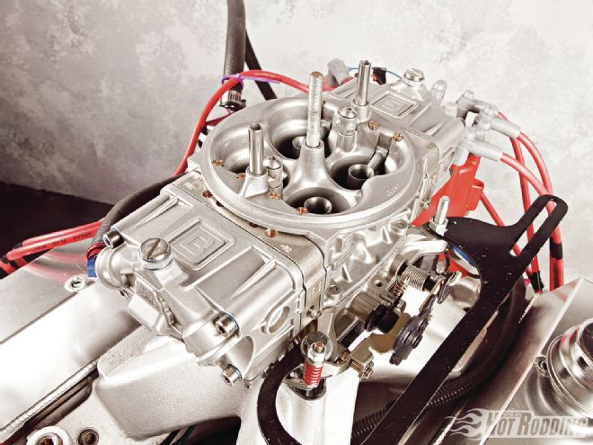 Tuning the 383 was fairly straightforward with the 4150-style carburetor from Braswell. Their carburetors have been found on a large number of NASCAR performers over the years, so it was no surprise that it only needed minor jetting and air bleed changes to make the best average power.
The brothers chose an Eagle Specialty Products 4340 forged steel crankshaft for their stroker. Cast or nodular-iron crankshafts are cheaper and lighter than their forged steel counterparts, but when balancing a long-stroke crankshaft, typically they require the addition of weights on the harmonic damper and flywheel. Externally balancing a crankshaft like that is fine for most low-rpm engines, but on higher-revving mills, that weight slinging around at the very ends of the crank forces it to flex around like a spaghetti string. The forged steel crank has the benefit of denser counterweights, which allow it to be balanced internally without adding weights on the flywheel and damper. In addition to a good balance job, Randy mentioned: “I knife-edged all the counterweights and profiled them. The majority of the profile is throwing the oil toward the main caps instead of toward the rods.”
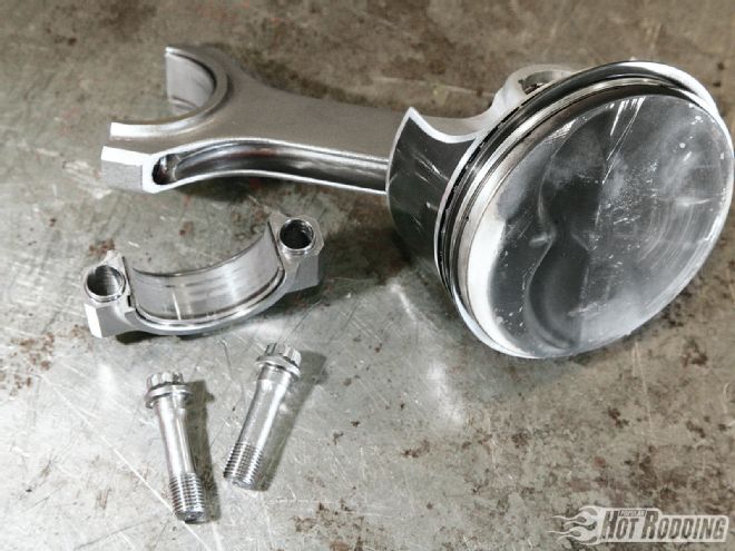
Eagle H-beam connecting rods were used to take advantage of their impressive strength-to-weight ratio, and the fact that they use incredibly strong ARP rod bolts. Aside from the high-tensile strength of the ARP bolts, one of the benefits of ARP is their dedication to constantly improving their products. One of the biggest, yet least known changes ARP made in the past few years was moving from a traditional “moly lube” assembly lubricant to a newly formulated assembly lube. Exciting right? Well, it should be. During testing, ARP found that their previous lube as well as oil and another test lube required several torque and release cycles before the fastener would pull a full load. Their new blend (in a blue packet that comes with the Eagle rods) pulls the full load right off the bat. Not only is this critical in rod bolts, but they found that head studs would apply the same clamping load everywhere around the head gasket the first time. Reality says that most guys building engines don’t torque their fasteners 8 to 10 times or use a bolt stretch gauge to be sure they are getting the full benefit of the fastener. Now the rest of us lazy bums can rest assured that the rod bolts and other fasteners are doing their job without worrying about it.
 Randy Ferbert modified the plenum of their World Products Motown intake by adding epoxy to form a cloverleaf. The effect was a smooth entry from the carburetor to the plenum with minimal turbulence.
SRP Professional series pistons have been around long enough now that people have realized what an incredible value they are. Randy says: “That’s probably the best bang-for-the-buck piston out there.” They have a forged side relief design, which basically means that the wristpin area has been made narrower but stronger. Strategically placed strengthening ribs support the piston under heavy loads. Though only mild nitrous hits are suggested for the pistons, we’ve personally run up to a 400 shot of juice on the slugs with nary a hint of problems (see PHR July ’08, “The Anti Dyno Queen”). Aside from making the pistons strong, they also make more power than the traditional SRP pistons. This is due to the low friction of a narrow, metric ring package. Even so, Randy says: “We replaced the standard-tension oil ring with an ultralow-tension oil rail. The short-block took about 11 pounds to rotate over. I was very concerned that we might have oiling trouble with that.” He said that everything worked out though, and with the aid of a header crankcase evac kit, they didn’t have any oiling problems.
 Though this was a “low compression” engine, it built a ton of cylinder pressures so the guys went to the big spark output of an MSD 7AL2 ignition box triggered by an MSD flying magnet trigger wheel. The trigger wheel provides a signal that is unaffected by timing chain stretch or cam flex. Coupled with a Pro Billet distributor, there was no problem lighting the fire.
As was mentioned above, those Ferberts know their way around cylinder heads. They chose to use a pair of cast-iron Bow Tie Vortec heads straight from GMPP. Though a lot of folks refer to all center-bolt valve cover cylinder heads as Vortecs, that isn’t quite accurate. The ’87-92 small-block–powered cars and trucks all used center-bolt valve cover heads. There were different port designs with regular- and high-swirl runner shapes throughout those years. When Chevy designed the Gen II small-block for release in ’92 Vettes and all other V-8 passenger cars in 1993, they kept the basic architecture of the engine the same as earlier models, but switched to dedicated reverse-flow cooling designed into the block and heads. Those LT1, LT4, and L99 (4.3L V-8) engines worked well, and the new cylinder head port design was much more efficient than previous small-blocks. The problem was, the Gen II was already a dead engine. The trucks had been continuing to use traditional “center bolt” heads through 1995, and the Gen III LS engines were waiting in the wings for passenger cars. GM had no plans to put the Gen III engines into trucks quite yet and wanted to continue to use a traditional small-block in their truck line, but somehow improve performance. The solution was simple. For 1996, they stuffed the intake runner design of the LT1 into a traditional casting, and labeled it the Vortec.
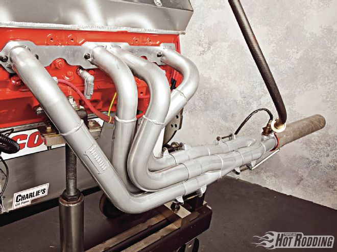 Schoenfield headers were used with a 4-2-1 primary system. Most applications tend to pick up midrange torque with that 4-2-1 design and are worth trying if there is room in the chassis.
Those Vortec heads not only flowed in the 230-plus cfm range (more than the iron Phase II Bow Tie racing heads of the time), they also had extremely efficient combustion chambers. Though the intake manifold bolt pattern changed a bit from the old-school small-blocks, aftermarket intake manifolds were instantly on the scene that would bring a basic 350 Vortec engine into the 375-plus horsepower range.
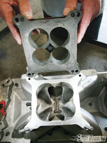 Part of the transition from the carb to the plenum was a custom carb spacer the Ferberts made. It expands evenly from the 1.69-inch diameter throttle bore outward in order to ensure a good solid signal to pull air through the dogleg boosters without being disrupted by any reversion.
GMPP saw the potential in the low-buck but efficient head design and came out with two new versions, which were available over the counter of your local Chevy dealer or through any of the normal catalog companies. (The 185cc runner is PN 25534421, and its big-brother 225cc is PN 25534446). Rick and Randy picked up a pair of the big-port heads and began a thorough examination followed by a plan to modify the heads for maximum effectiveness.
Building a head for mass markets is one thing, but designing a head for a specific application is an entirely different undertaking. There are very few compromises to be made since there is only one engine for which it is destined to live on. There is only one specific power range for which it must create the perfect power curve. With that in mind, it was almost easier to design the runners than it would be for something that would be run on a variety of engines and conditions.
The act of designing a runner requires equal parts art and science. The science begins by understanding the engine cycles. It is actually easiest to begin talking about that at the point of top dead center on the compression stroke. Both valves are closed. The ignition just lit off the air/fuel mixture, which is slowly expanding. About 15 degrees after TDC, the flame front is kicking into high gear and building tremendous cylinder pressure. By the time the piston is about an inch down the hole, the fast-burning gas has done most of its work, and the piston is just along for the ride. In order to get a jump on getting all that burned exhaust out, the exhaust valve starts to creep open somewhere around 40 degrees before bottom dead center. Opening that valve early is called blowdown and is one way to help the efficiency of the engine. Since the gasoline is already burned but there is still high pressure in the chamber, that exhaust will start to move out the exhaust port before the piston starts coming back up. Once that piston is on its way back up, there are pumping losses as that high pressure in the chamber is still slightly trying to push the piston back down.
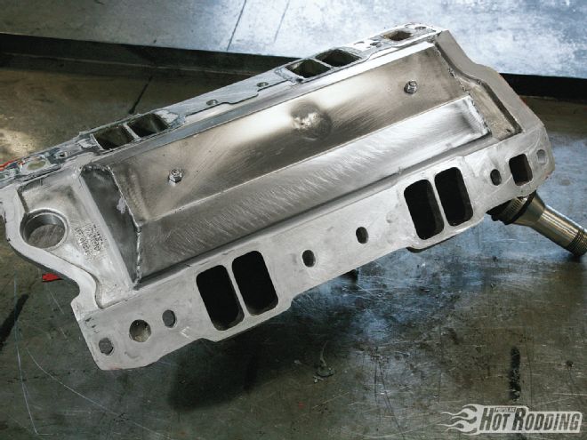 Keeping the intake manifold cool is well known to help make power. The Ferbert brothers fabbed up a simple heat shield to keep hot oil from splashing up onto the bottom of the plenum.
About the time the piston is two thirds of the way back toward TDC, the velocity in the header pipes gets high enough to actually help lower the residual cylinder pressure some. This is due to the fact that (science here still) as velocity increases, pressure decreases. Unfortunately not all of the pressure in the chamber has subsided by the time the intake valve starts to crack open just before TDC. This puts the exhaust gas in a dilemma as it wants to go out both the exhaust and the intake valve. Some of that exhaust gas does, in fact, get shoved back up the intake tract in a process known as reversion. Finally, that low pressure in the header pulls the remainder of the exhaust out just before the exhaust valve closes a few degrees after TDC.
Now the intake valve is on the move. After creeping open with a slow and steady opening ramp, the valve now moves at maximum velocity to get to maximum lift. The piston is moving down the hole rapidly and by the time it is around 73 degrees ATDC, it is moving at maximum piston speed of an incredible 4,000 feet per minute when this little 383 is turning 6,500 rpm. That’s 45 mph folks. Let that little tidbit sink in real quick. The piston just went from 0 to 45 mph in .002 seconds. Awesome. Back to the intake valve though. It is chasing that piston down the hole while there is a growing vacuum in the combustion chamber drawing fresh air and fuel in. The piston rounds BDC and starts to come back up but the air blasting down the intake runner is moving so fast and with such energy that it continues to come in all the way until the intake valve closes around 40 degrees after BDC when the true act of compression, dynamic compression as they say, begins. Then the cycle starts over.
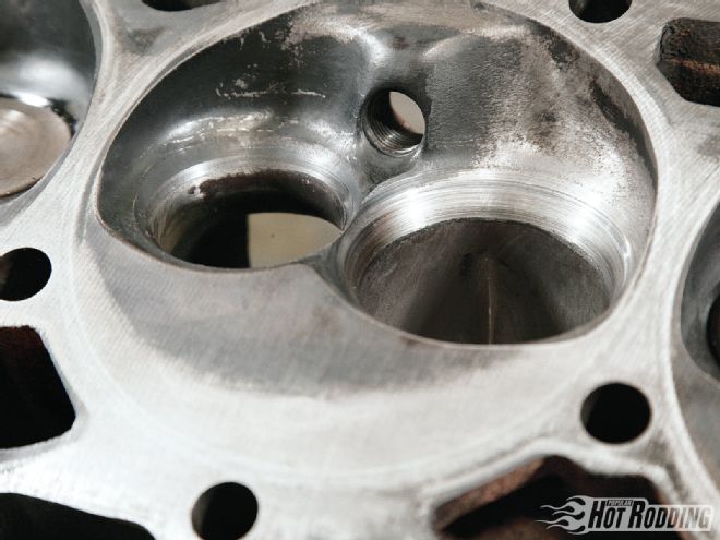 The Vortec combustion chamber is worlds ahead of the old-school SBC designs. Very little work beyond smoothing it out was performed. Proof of an efficient chamber is seen in the fact that the engine needed very little ignition timing to make the best power.
The Ferberts, of course, know all this. And they use this knowledge in every step of designing their runners and valve jobs. For that exhaust port, they wanted something that was unrestrictive, yet not so big and blown out that it wouldn’t create good velocity. It is, in effect, an extension of the header tube bolted up to it and as we have seen so many times in the past, a moderately sized header pipe can make significantly more torque than a huge header pipe.
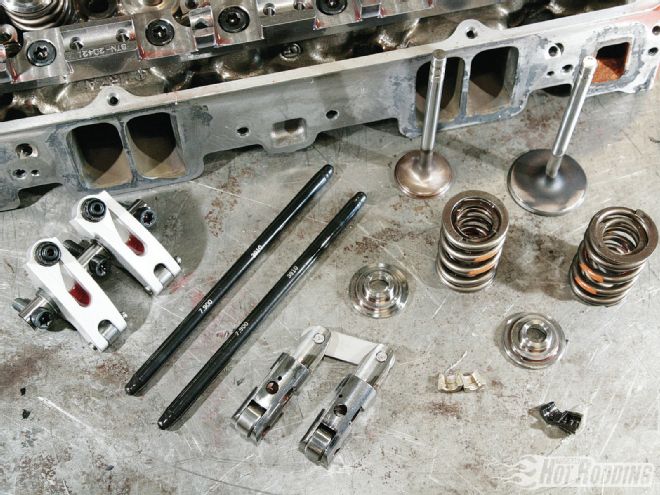 Though the engine was designed only to run to 6,500 rpm, valvetrain control was still deemed important enough to use Jesel shaft rockers and heavy-duty ⅜-inch pushrods. Per EMC rules, lift was limited to .650 inch and Randy’s cam was .010 under that, but they were still able to run a solid-roller cam. He mentioned that the COMP cam they ran ended up with a hydraulic-roller intake lobe and a solid-roller exhaust lobe for best performance.
Choosing a valve job for the exhaust, the brothers considered that they wanted to ensure maximum flow with minimum restriction while the piston was on its way up, but didn’t want to waste too much of the still-expanding gasses during blowdown. They decided a 50-degree valve job would satisfy those needs. The 50-degree valve job traditionally trades some low-lift flow for a gain in higher-lift flow. Picking the right exhaust valve opening and closing points gets a little trickier when veering away from the traditional valve jobs and flow curves.
If designing the exhaust side was a little tricky, the intake side gets downright treacherous. When that intake valve was just cracking open during split overlap, the boys wanted to keep the reversion to a minimum but still allow the valve to start moving open or it would never get enough lift in time to take advantage of that incredible vacuum in the chamber at max piston speed. To quell some of that reversion, a 50-degree valve job was performed on the intake as well.
After figuring out how they wanted their valve job, they moved on to the actual runner design. They wanted a minimum cross-sectional area (MCSA) that would at least be physically capable of moving enough air so the engine wouldn’t starve at the peak rpm range of 6,500 rpm. But they wanted to be sure it was small enough that it would create a ton of velocity, which would aid in cylinder filling. An MCSA number of 2.06 square inches was picked and the boys went to town adding some epoxy in areas that, according to a velocity probe on the flow bench, showed little air movement. Dead areas. At the same time, they focused on grinding areas that showed excessive velocity, bordering on turbulent. Typically that means that good target air speed is around 300-350 feet per second. Below 275 fps is considered lazy, and over 400 means the air is on the verge of shearing or choking the port. Mapping out the port while porting and flow testing, they came up with an incredibly efficient design that gets the job done better than the vast majority of heads available. “I tried to widen the radii to make the port more efficient. I tried to make the port as straight as I could make it, and as even a speed as I could. On a 23-degree head, that’s about impossible.” Randy did a good enough port job that the heads ended up flowing about 290 cfm at .650-inch lift through a final runner volume of 204cc. Not half bad.
 The SRP Professional Series pistons come with Teflon-coated skirts to reduce friction and deburred valve reliefs to avoid detonation from hot spots. Normally they come with a standard tension oil ring, but to get the most power from the combination, they swapped to an ultralow tension oil ring. They feared there might be some oil pumped up into the chamber since they didn’t have a vacuum pump. Nevertheless, with the perfect hone job on the block, there were no issues.
With the heads and bottom end built, the guys spent some time on the dyno trying a few different camshafts to see what would perform best. For some reason, regardless of the duration or lobe separation of the cam, the engine always made the best average power when it was set up to close the intake valve at 42 degrees after BDC using the .050-inch tappet lift reference. That appeared to be the point where the gains from holding the valve open to let more air in coincided with the gains from closing the valve and starting to compress the air fuel mixture. Randy said that regardless of the duration or lobe separation of the cams he tried: “We found more score with cam position rather than the actual cam changes.”
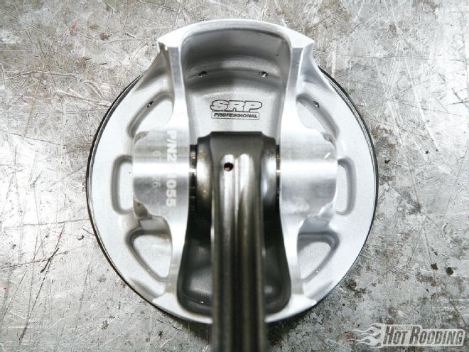 The forged side reliefs are easy to spot here as they cut out a ton of weight from a traditional “full round” piston design, yet maintain strength.
With the engine now complete, Rick and Randy packed up with their crew and headed to the University of Northwestern Ohio in Lima to see how their bucks-down engine would fare against the high-dollar competition. After student volunteers bolted their mill to the DTS dyno, they ran a fresh batch of VP fuel through the Braswell carburetor and fired the engine to life. It purred like a kitten at idle but howled like a lion under full load through the Flowmaster mufflers. The dyno sheets spit out the facts that this little cast-iron pump-gas–friendly street engine made an incredible 606 hp. The brothers proved that not only could such a powerhouse be built on the cheap with a bit of thought and preparation, it could be replicated by almost anyone and outperform some of the best bucks-up crate engines on the market.
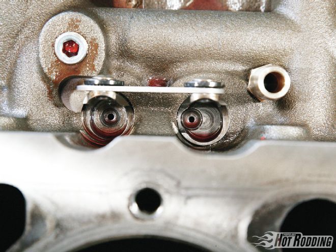 Offset intake lifters allow maximum widening of the intake runner at the pushrod pinch without fear of grinding through into the lifter valley. They also make the pushrod sit straighter and have less parasitic energy losses from a pushrod sitting at an angle.
“Their plan was deceptively simple. Build a basic 383 combo using off-the-shelf components…”
The 50-Degree Valve Job
In the Apr. ’12 PHR, we brought some basic valve job tech issues to light. Thanks in part to the information given by Rick and Randy Ferbert, we were able to expand on the effects of using a steeper-than-normal valve job angle. When the valve begins to open, say .050 inch for example, there is a certain amount of area that is opened up between the seat and the valve. This is called the curtain area. In general, the curtain area is described as the circumference of the valve multiplied by the lift:
Ac = ∏ × Valve Diameter × Lift
This formula works well for general conversation, but is a little lacking when it comes to the finer elements of valve job design. The problem is that the above formula only takes into account a valve job where the valve seat is at 90 degrees, and sits at the very edge of the valve. If you start moving the edge of the valve seat inward so that the smallest part of the valve job contacting the valve is, for example, .050 inch in from the edge of the valve, then that area will obviously be smaller. Additionally, by changing the angle of the valve from 90 degrees to something like 45 degrees, the distance from the valve to the seat is no longer a direct 1-to-1 correlation to valve lift. As seen in the illustration, when the valve is lifted .050 inch, the gap between the valve and the seat is only .035-inch wide. Obviously, there needs to be some corrections in the formula. The true formula for the valve curtain area becomes:
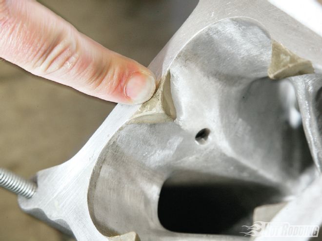
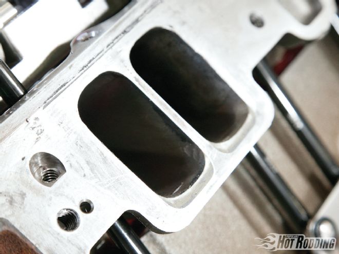 Randy added epoxy to the floors of the runners to give them a slight raised-runner effect. Brand names vary on the epoxy used but a number of head porters use Z-Spar or Splash Zone epoxies, which were actually designed to repair boat hulls. The good news is the epoxy resists gasoline. The bad news is alcohol (and high-ethanol gas) eats away at it.
Ac = ∏ × Lift × cos (valve angle) × (valve diameter − [seat width × 2 × cosine (valve angle) ] )
Comparing the “general” formula to the “true” formula with a traditional 45-degree valve job, we see quite a difference in curtain area:
∏ × 2.08 × .050 = .327 square inch with the general formula
∏ × .050 × cos (45) × (2.08 − [.050 × 2 × cos (45) ] ) = .223 square inch with the true formula
Now comparing the .223 square-inch curtain area of that 45 degree valve job with the Ferbert’s 50-degree valve job we see a big drop in curtain area:
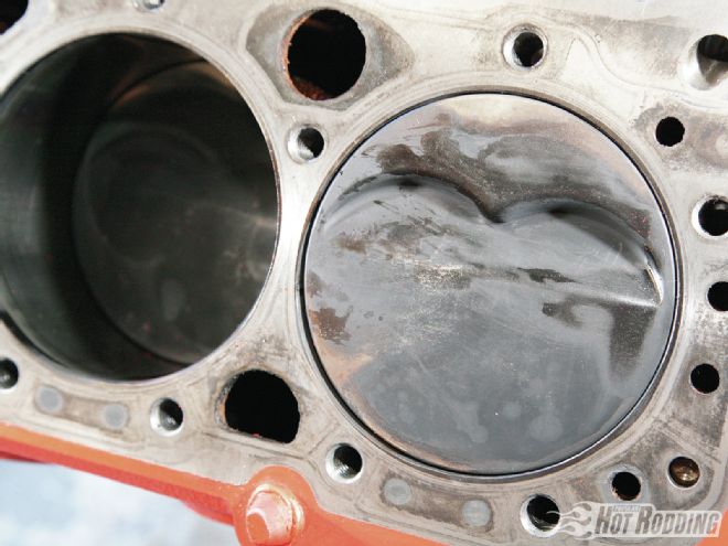 A clean burn pattern on the top of the piston confirms that the combustion chamber shape was doing its job in evening out the burn. There is also very little evidence of wet fuel washing down into the chamber. That should lead to very low and efficient brake-specific fuel consumption numbers.
∏ × .050 v cos (50) × (2.08 − [.050 × 2 × cos (50) ] ) = .204 square inch
What all this boils down to is that the 50-degree valve job has almost 10 percent less area that the air gets to pass through. That explains in part why flow bench numbers show that usually a 50-degree valve job has smaller low-lift flow numbers and helps kill reversion.
The second thing about a higher angle valve job is, once the intake valve starts moving up in the lift range, the 50-degree seat actually starts flowing more than the 45-degree valve job and is able to get more air into the chamber when that piston is pulling hard.
Yes, most of us car guys avoid math whenever possible, but spending a few minutes with a calculator now and then isn’t so horrible, especially when you start figuring out ways to make more power. Rick created an Excel spreadsheet to make all that math a little easier to use (if using Excel, then you need to convert degrees to radians first, radians = (deg × ∏ ÷ 180). By using the numbers generated there, they deduced that the steeper angle valve job would make the engine think it had a shorter duration but higher-lift camshaft, since the air would get moving later but eventually pack more in.