
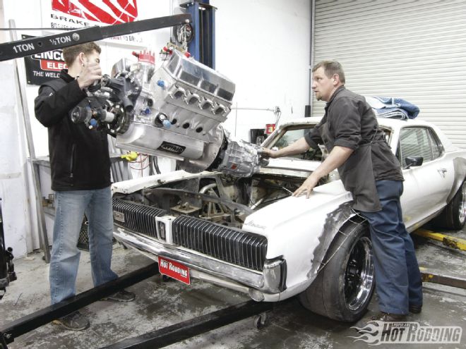
It’s admittedly been a while since we last wrenched on our ultimate incarnation of a street-legal road racer known as Max Effort, but we’re ready to get serious again. [Editor’s note: Last time was the Nov. ’11 issue, when we built the ’67 Cougar’s rollcage.] Now we’ve got a big step forward to kick things off again: We’re dropping in the drivetrain.
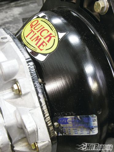 It’s likely overkill since high-rpm drag launches aren’t in our plans, but we opted to run an SFI-approved QuickTime bellhousing from Lakewood Industries for the extra safety margin. We’ll never have to be concerned about clutch failure of any kind throwing shrapnel into the car (or our feet) no matter what we put Max through down the road.
But this isn’t just a simple bolt-it-to-the-mount operation. Since Max Effort makes use of CorteX Racing’s vintage competition suspension, which includes a complete swap over to a K-member much like modern muscle cars use, our options are wide open for engine placement. Typically, the CorteX K-member would be equipped with standard mounts for a small-block Ford, modular Ford (including the Coyote), or GM LS, depending upon the customer’s engine plans, but ours is sans mounts of any type. That’s intentional; we have no plans to use the block mounts. We’re going for the kill and building an engine plate.
Why an engine plate? Well, we’ve got two thoughts working together here. First and foremost we can create increased rigidity on the front of the chassis by strategically tying the two sides of the rollcage and the framerails together. We’re also planning to set the engine back and down significantly for better weight distribution, so trying to use stock-style mounts becomes more of a chore than a convenience. Besides, by eliminating the block mounts we gain the added benefit of a very open area for the custom headers that we’ll need to build down the road.
For rodders who aren’t so concerned with those points, there are several other key benefits to positively locating the engine. You’ve likely seen racers at the track who’ve added a torque link to one side of the engine to prevent torque roll. That’s essentially because any side-to-side motion of the engine is just wasted energy that’s only doing two things: creating a slight loss of power since ideally we want the driveline to transmit all of its power through the crankshaft, and straining the mounts and the bosses they are bolted to. Additionally, that sideways roll can affect how a car handles as it creates a rolling force to one side of the car. That’s never good when you’re hard on the throttle.
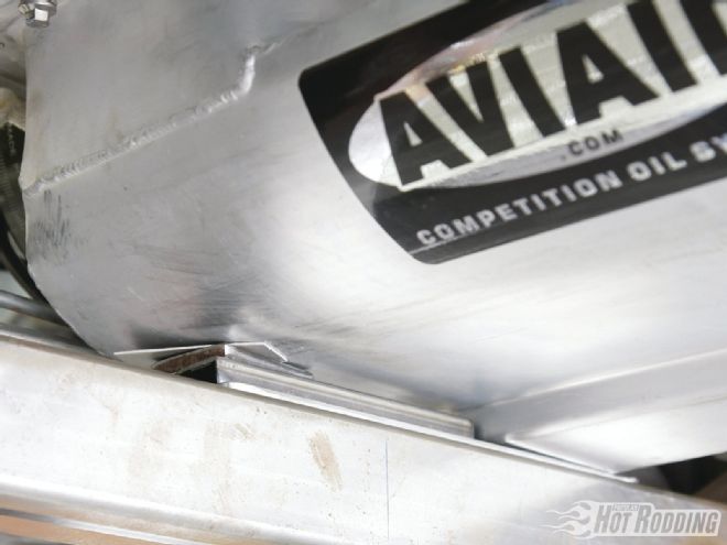 Since we’ll be eliminating engine roll from the equation, we only need a bare minimum of clearance for the pan to the crossmember. On the sump side of the pan we have about ⅛-inch clearance.
Solid engine and trans mounts might be the obvious go-to choice for eliminating the twist, but solid engine mounts transmit a massive amount of stress into small points on the sides of the block. The higher the horsepower, the more of an issue this becomes as the pushing and pulling forces can actually slightly deform the block under WOT. At a minimum, damage to the engine mount bosses can occur. By contrast, an engine plate works to distribute the stress on the block more evenly. Our 715hp 438ci Clevor from Ford Performance Solutions generates plenty of power to make all of that a concern.
To make sure we’re channeling all of that power where we want it and not creating any adverse conditions for handling, we’re once again trusting the experience of talented fabricator Ryan Kertz at Kertz Fabrication in Sonoma, California. His years of experience building road race and extreme street cars are exactly what we need to make the most of our engine placement.