
With our project engine block fully machined and the Butler stroker kit balanced and checked, we are almost ready for preassembly using the myriad performance parts that were provided by Summit Racing Equipment, but that will be covered in the next issue. First, RaceKrafters will attend to our 6X Pontiac head castings.
This installment will be of particular interest to HPP readers, since these are the only procedures that can be applied sans a complete engine rebuild. A Pontiac may have its cylinder heads removed for a valve job, failed head gasket, porting for improved power, or swapping to a more efficient design. Regardless of the reason, all of the steps showcased in this primer can apply.
As is true for block and rotating assembly work, a complete inspection and application of all machining procedures should be implemented. The cylinder head is a paramount component, not only to the engine’s potential power production but to longevity as well—no shortcuts should be taken.
We will showcase through photographs the actual work performed on the mule’s cylinder heads, while the text will expand on those procedures and speak about some others that do not apply to our application. The goal is to educate our readers on the steps required for proper engine building even if in your case you may only be working in one area.
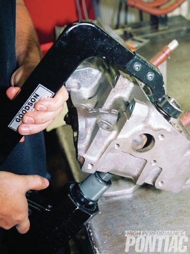
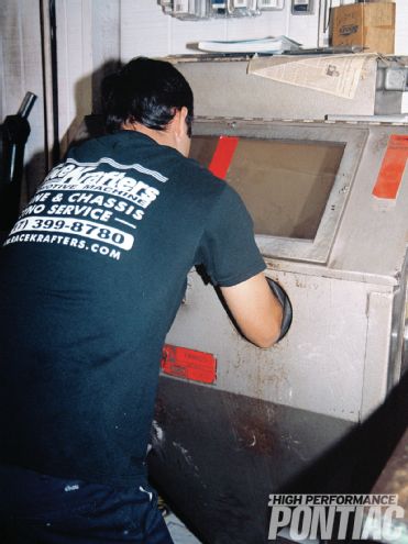 1 Once a used head is stripped and visually inspected, it will be cleaned up in the bead-blast cabinet, as RaceKrafters’ Corey Porter illustrates, or through another means, such as a jet wash or hot tank.
Disassembly, Cleaning, and Inspection
Once the cylinder head is removed from the engine, it’s advisable to tag the rocker arms and pushrods unless new components are going to be purchased. It’s also a good idea to retain the head gaskets and mark them for each side of the engine. Carefully remove them from the block and look for an even imprint on both the cylinder head and block deck surfaces.
Before leaving the engine block, use a thick motor oil, such as a 50W rating, and with your hands or a new, clean paint brush, coat the cylinder walls and deck of the block to prevent corrosion. Securely cover the exposed parts of the engine block with either a plastic trash bag of the appropriate size or with a cling-type plastic wrap.
The machine shop will do a quick visual inspection of the heads and look for damage, such as cracks and valve-seat recession. When recession occurs, the valve will actually start to pull through the cylinder head at the seat—the surface the valve closes against. The seat then starts to migrate further into the casting.
 2 It is important to pressure check a cylinder head before any work is performed. This may also be done again after porting and especially if valve seat inserts are installed.
Once the shop thinks the cylinder head is acceptable, it will disassemble and clean it, and do a more thorough inspection. Cast-iron heads can be magnafluxed using the same procedures that are employed for an engine block and crankshaft.
Cylinder heads need to be pressure-checked using an application-specific machine to confirm that no cracks exist. Aluminum heads can sometimes crack in between the seats for the intake and exhaust valves due to the lack of material in this area and its high exposure to heat. If any damage to either a cast-iron or aluminum cylinder head is discovered, a decision to repair or replace it needs to be made. The cleaning process is usually similar to that of a cylinder block—they can be hot-tanked, jet-washed, or placed in a bake-off oven. Aluminum cylinder heads are not hot-tanked due to the impact the cleaner has on the material.
Valves will be inspected for wear and to see if there is a sufficient margin left to re-cut the necessary angle and still maintain enough mass for cooling. The margin is the flat surface on the side of the valve head that is just below the face of the head if held with the stem toward the ground. If it’s worn away, then the valve will need to be replaced. If it’s put back into service, it will fail prematurely by loosing its shape and not provide a good seal against the seat.
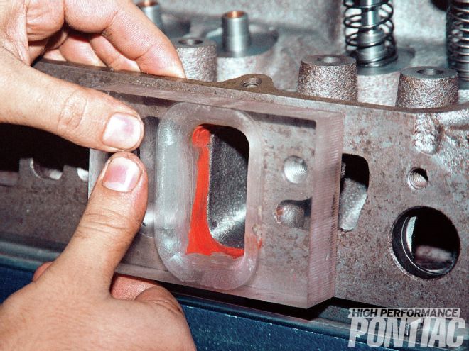 3 Corey installed a plexiglas radius on the intake port for accurate flow bench testing. This allows the air to enter the port and not shear.
Cylinder Head Equipment
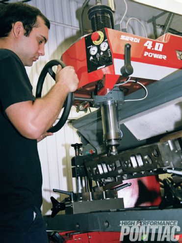
To service cylinder heads properly, a professional will have a machine referred to as a “head shop.” RaceKrafters employs a state-of-the-art Serdi 4000. The head shop will cut the angles in the seat, bore the seat out for replacement, hone or index the valveguides, and cut them to length. A valve grinder is a separate machine that is used to form the angle on the valve head and also grind the tip perpendicular to the head and stem. The tip of the valve wears as the rocker arm drags and pulls across it and so will become slightly grooved. Stamped-steel rockers actually end up pulling the valve against the guide, causing not only wear on the guide and tip, but high oil temperature at the contact point.
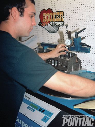 4 He spent a good deal of time on the flow bench with the 6X heads not only to maximize flow but to make sure all ports are flowing evenly. A special fixture is used to open the valves, along with test springs instead of normal valvesprings. A dial indicator registers the lift.
Surfacing of the cylinder-head deck is done on the same equipment used to machine an engine block and requires a special fixture to attach the casting.
Perhaps the shop does not use a head shop and instead uses grinding stones attached to an application-specific heavy-duty drill to form the necessary angles on the seat. Though this is a commercially acceptable procedure for non-performance work, it’s not as exacting as a cutter, and may impact the airflow potential of the engine.
A shop that only performs cylinder head work may not have a rotary cutting or broaching machine and may instead use a large belt-sander to deck the head-gasket surface. It is the author’s opinion that this procedure is not acceptable for any engine and is customarily done as a very cheap rebuild by a high-volume shop. Services such as belt-sand surfacing are often referred to as “taxi-cab-style” and have no place on a high- quality Pontiac engine rebuild.
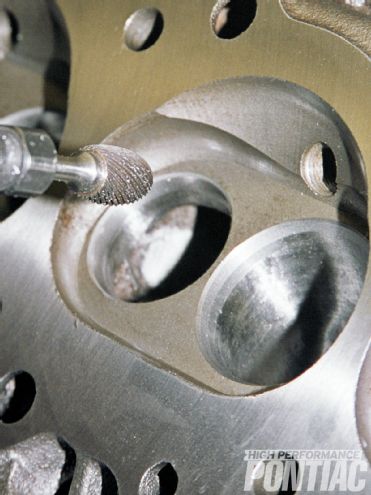 5 When developing a port, the operator goes back to the workbench to remove and reshape material many times. Here Corey is using a cutting bit for the exhaust port.
ValveGuides
Most if not all Pontiac cast-iron cylinder heads came from the factory without any valveguide inserts. This design had a boss with substantial mass cast into it that was drilled for the valve to reciprocate in.
Valve stems and guides need to be checked for wear. Excessive stem-to-guide clearance allows air and oil to be drawn into the combustion chamber. This will result in a rough idle, increased oil consumption, fouled spark plugs, and an excessive build-up of carbon in the cylinder. Valveguides will typically bell-mouth at the top and bottom. The direction of wear is in line with the rocker arm movement. Valve-stem wear will be the worst at the extreme top and bottom of the guide rub area.
 6 Once the port shape is finalized, he smoothes and polishes it with a sandpaper roll often called a “Tootsie-Roll.”
There are several methods for measuring valveguide wear. These include:
1 Inserting a telescoping or split-ball gauge to size the guide. The gauge is then removed and measured with an outside micrometer.
2 Employing a special valveguide dial-bore gauge that works similar to a cylinder bore gauge but is much smaller in size.
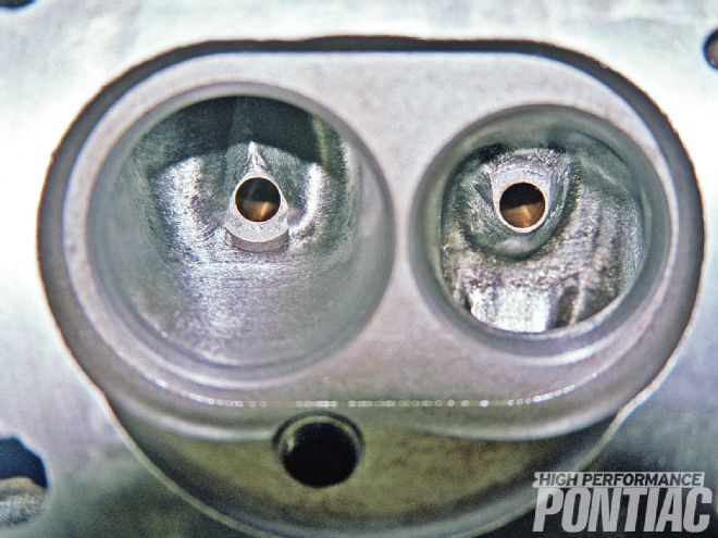 7 This is the finished Super Mod Porting job. All volumes were checked and resulted in a 140cc exhaust port, 172cc intake port, and a 96cc combustion chamber.
3 Inserting a new valve into the guide with a dial indicator positioned at a right angle to the stem. Then the stem of the valve is rocked back and forth against the indicator plunger. If the clearance is more than specified, the guide is worn.
4 Valve grinding pilots are often used as a go/no-go gauge, but this method is the least accurate since it’s difficult to quantify an egg-shaped guide.
The valve stem is best measured for wear using a micrometer.
A good rule is if the valveguide clearance exceeds the shop manual specifications by 50 percent, replace or repair the guide. If specifications are not available for your engine then use 0.003 inch as the maximum for intake guides and 0.004 inch for exhaust guides. RaceKrafters set the valveguide clearance to a very precise 0.0014-inch using a diamond honing stone (more on this later).
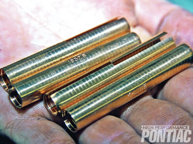 8 The 6X castings were going to be treated to bronze valveguides for precise oil and air leak control.
Aluminum cylinder heads traditionally use bronze valveguide inserts for durability and its lubrication properties.
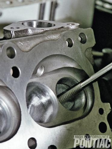
Though many procedures exist to repair worn integral guides in cast-iron cylinder heads, most experts believe that if the guide is worn, the best approach on a Pontiac engine is to install a bronze insert into the boss. The head shop machine is used to drill the old guide diameter out; a new bronze guide will be installed with an air hammer. The head shop is then used to cut the guide to the desired length. A very high-quality machine shop will carry this one step further and install a slightly undersized inner-diameter guide and then hone the guide to create the desired valve stem-to-guide clearance. A hone of this nature is usually fitted with diamonds and can hold very close tolerances, down to 0.0002 inch.
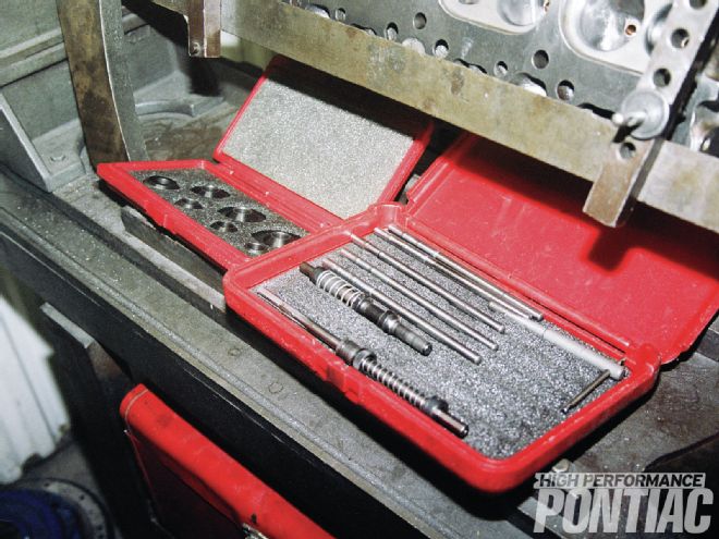
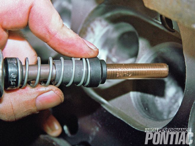
9 A special tool kit is required to install the bronze valveguides after the old guide holes are bored.
If inserts are not going to be installed, then the guide in a cast-iron head can be reamed and a valve with an oversize stem can be installed. Valves are usually offered for most engines with 0.003, 0.005, 0.015 and 0.030 oversized stems. Aluminum heads with worn guides usually are serviced by driving the old guide from the head and pressing in a new one.
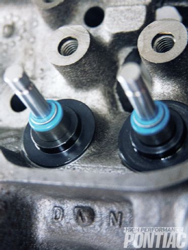
Valve-stem seals are installed over the guide and are used to control the amount of oil that gets in between the valve stem and the guide. There are a number of different types of valve seals—some rest over the guide, while others attach to the valve stem itself.
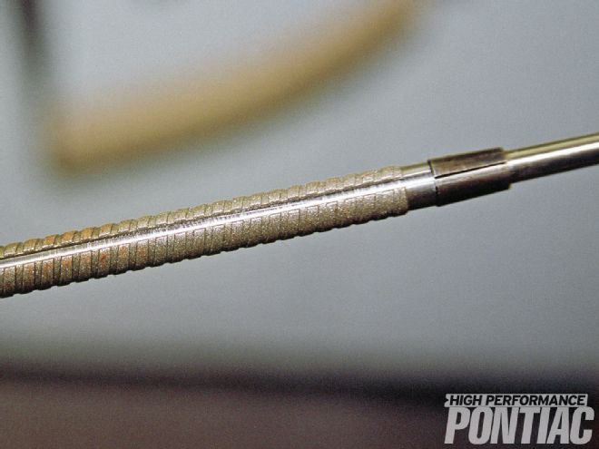
 10 With the proper size hole created, Corey starts the guide into it for installation.
The most effective is called the positive insert style. This design is held securely to the valveguide with an internal spring ring for tension. Although a number of companies make this style seal, many refer to it as the Perfect Circle or PC seal (the original brand). It boasts exceptional oil control, while prohibiting the passage of air through the guide. It’s offered in sizes from standard to 0.015-inch-oversize valve stems. PC seals are easy to install but some cylinder heads will require the top and side of the guides to be machined in the head shop to accept them.
Valve Seats
Most, if not all, Pontiac cast-iron cylinder heads came from the factory with no valve seats. Instead it had the necessary angles cut into the cast-iron material, forming an integral seat. In many applications, this area was hardened by the factory using electricity through a procedure called induction hardening.
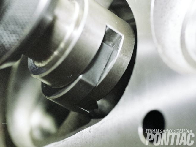
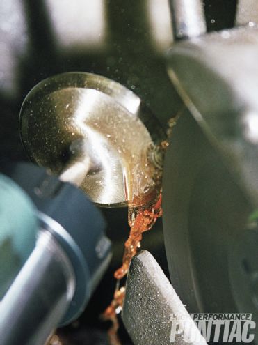
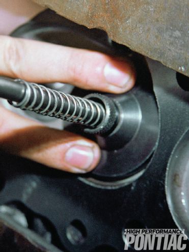 11 He uses an air hammer with a special adapter to drive the bronze insert into the cylinder head. He then cuts it to the proper length using another tool.
With years of use, the machine shop may find that the material left in the original seat is no longer sufficient. In this instance, hardened seats need to be installed—the same type of seat used in an aluminum cylinder head. The procedure entails locating the center of the bowl through the valveguide and then counter-boring the area where the integral seat originally was. The head shop machine is used for this. The new hardened seat is chilled in dry ice (minus 112 degrees F) or with Freon to shrink it and then it’s quickly driven into the counter bore before it warms. As a precaution, the seat may then be staked, or through the use of a special tool, a metal edge is formed that rolls over the surface where the seat and head mate, preventing it from falling out. If the seat drops out while the engine is running, it usually results in catastrophic damage to the block and cylinder head (more common with aluminum heads if the engine is overheated).
An issue with installing seats in an older cast-iron Pontiac cylinder head is that a good deal of material needs to be bored out to accept it. The problem is an erosion of material from interaction with the coolant—the cylinder head is usually very thin in spots from years of use. When the integral seat is bored out to accept the insert, the water jacket passage is broken into and the head becomes unusable for all intents and purposes. Thus, it is advisable in most instances to not install a steel seat insert if the integral seat area is in good shape and can be cut to the proper angles.
 12 RaceKrafters is very precise with its work, and likes to install an undersize guide and use a diamond hone in the head shop to create the proper clearance.
There was a big push nearly 40 years ago when unleaded gasoline was introduced to modify the cylinder heads. It was said that a Pontiac and other cylinder heads would need to be fitted with steel seat inserts or the valves would burn from the unleaded gas. The same was stated about installing bronze valveguides. As we now know this is not true. That myth needs to be finally put to bed, especially when production Pontiac cylinder heads are getting harder to find.
 13 Corey carefully honed the new guide. He set the clearance at 0.0014 inch on all guides.
Surfacing the Cylinder Head Deck
Part of a proper head rebuild is to surface the deck to make sure it will be parallel with the deck of the block. Often this step is overlooked, along with the fact that the finish of the deck needs to be approximately 30 RMS for cast-iron and 60 RMS for aluminum, the same as the block. The amount of material removed needs to be recorded because on a V-style engine if more than 0.010 inch is machined off, then a correction for the intake manifold will need to be made. If this is not done, the intake manifold will not seal properly and can cause either oil or air leaks, or both.
 14 Here the valve-seat area is being cut. The intake angles are 45-degree seat, 60-degree, 75-degree, and 82-degree hand-blended to 75 degrees. The exhaust is 45-degree seat and a 12mm radius.
When manifold correction is required, the proper approach is to modify the cylinder head surface instead of cutting the intake manifold. This way an out-of-the-box intake can be used and different manifolds can be tried. On a standard rebuild, a small “clean-up” cut is recommended and will not create any sealing issues.
When a higher compression ratio is desired, the cylinder head is milled to decrease the combustion chamber volume to alter the static compression ratio of the engine. For this to be done accurately, the cylinder volume with the piston at TDC needs to be measured, along with the volume of the combustion chamber and head gasket. Once this is determined, the head can be milled to a desired combustion chamber volume. This is a tedious task since the machinist needs to cc the combustion chamber with the head on the decking machine. Through experience, they will know more or less how much material to remove. As they “sneak-up” on the final dimension, the combustion chamber volume may need to be measured a few times. If an excessive amount of material needs to be removed, a procedure called angle milling can be performed.
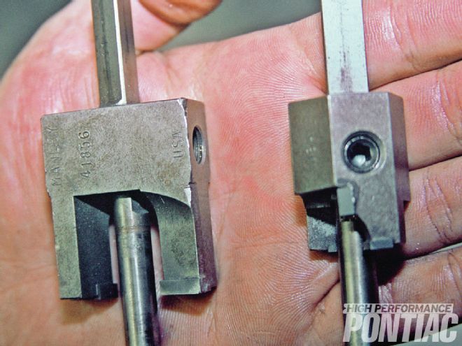
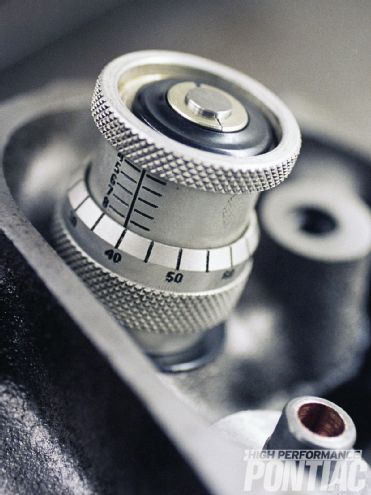 15 A valve-height micrometer is a fast and accurate way to determine the distance from the spring seat to the bottom of the retainer.
Valve Job
The installation of the necessary angles on both the valve itself and the seat is the valve job. Since both valves spend more time traversing their lift range than dwelling open, the angle and accuracy of the valve job is paramount to the performance of the engine.
Low-lift flow on both the intake and exhaust valves is dramatically impacted by the valve angles. As the valve moves away from the seat and combustion chamber wall it becomes unshrouded. The valve angles become less critical, but still play an important part in the air throughput of the engine.
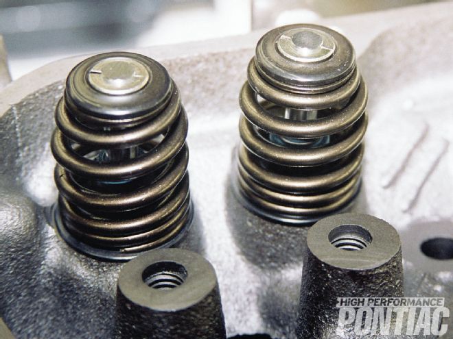
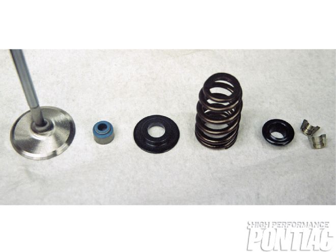 16 RaceKraters carefully machined the spring seat area so that no shims would be required and a hardened spring seat could be employed. Shown are a valve seal, and the Comp Cams hardened seat, valvespring, retainer, and locks that were provided by Summit.
The head shop is used to cut the angles into the valve seat, and the valve grinder imparts the proper shape on the valve itself. A common performance procedure is a multi-angle valve job. By integrating more angles into the seat, the airflow is increased by gently steering it instead of forcing abrupt turns.
Contrary to popular belief, most cast-iron cylinder head Pontiac engines came from the factory with only a one- to two-angle production valve job. This was due to the use of an integral seat and a cost/benefit ratio for manufacturing. Back in the day, many cars that were sent to the press fleet and were tagged as “ringers” had much attention paid to the valve angles. The difference between a cheap and high-performance valve job is the amount of effort taken to create the angles.
 17 Each Comp Cams valvespring was tested and the pressure at the installed height of 1.700 inches was 137 psi. At 0.550-inch valve lift (spring compression to 1.150 inches), the pressure was 290 psi.
Porting
Porting of a cylinder head returns the most bang for the buck, especially if the camshaft and intake manifold are also changed. Reshaping cast-iron is a very tedious and time-consuming task and is one of the reasons most performance cylinder heads are made of aluminum. Others are cost, weight, and heat dissipation.
The three areas where a cylinder head can be ported are the bowl, which is the area behind the valves; the intake and exhaust runners (ports); and the combustion chamber. Blending the bowls and doing a good valve job results in the biggest gains in airflow.
 18 This is the tool that is used to precisely cut the spring seat in the cylinder head.
Bowl blending or pocket porting is used to match the final angle of the valve seat with the bowl of the cylinder head, while also removing any casting imperfections and parting lines. This service is essential when a hardened seat is installed in either a cast-iron or aluminum head. It results in a radius of metal where the seat pocket is cut, effectively choking air flow and decreasing the size of the throat.
Runner porting can be as little as a gasket match that forms a radius at the joining area of the cylinder head port and intake manifold, all the way to a complete reworking of the runner and teardrop shaping around the valveguide. The combustion chamber is not considered to be ported, but instead is recontoured and smoothed to allow better and faster flame travel.
For our project engine, RaceKrafters performed its “Super Mod Porting” on the 6X heads. Its bowls were completely opened, and the area around the valveguide was teardrop shaped to improve flow. The runner of both the intake and exhaust ports were also opened up and modified for improved breathing. Its combustion chambers were polished and slightly recontoured to improve flame travel and smooth airflow. A good deal of attention was paid to the valve angles for superior low lift flow.
 19 A high quality positive lock seal was installed on every valveguide. The distance from the valve seal to the retainer was 0.630 inch, allowing us to install a higher lift cam in the future. The cylinder head undergoes a pre- assembly for checking purposes before all the work is complete.
All of this provided stunning results, as seen by the flow numbers derived on the Super Flow 1020 test bench. All results are at 28 inches of water depression with a radius inlet and no exhaust extension.
Setting Spring Pressures and Installed Height
Valvesprings not only need to be matched to the camshaft but also the cylinder head. Springs are chosen by diameter, pressure at the installed height, and open or nose pressure (the force when the lifter is on the nose of the camshaft).
Often the machine shop will use the head shop to cut the spring pockets or area where the spring sits to achieve a desired installed height, which is the distance from the bottom of the retainer to the spring seat pocket. If this is not done, then shims may be used to alter this relationship.
 20 Corey checked and cut all the valves to work in conjunction with the seat angles installed by the Serdi 4000. When the valves are being modified they are bathed in a coolant/cutting oil.
A spring tester is used to determine the pressure at the installed height and a height micrometer is employed to find this distance. Though a conventional vernier caliper can also be used to measure the installed height, it’s more burdensome and allows room for error.
Aluminum cylinder heads require a shim or steel seat under the valvespring to keep it from galling the spring pocket.
Valvesprings should never be installed out of the box without being checked for pressure at the installed height and fully open. When a high-lift cam is installed, the spring also needs to be checked for coil bind. There should be a minimum of 0.060-inch clearance between the coils when the valve is fully open. This can be checked with a feeler gauge. Coil-bind on our 455 did not occur until a valve lift of 1.050 inches.
21 A pneumatic valvespring compressor was used to assemble the cylinder heads.
Rocker Studs
Most low performance cast-iron cylinder heads have rocker studs that are interference or press fit into a boss that is cast into the cylinder head. A stud puller is required to remove them. The new stud is then pressed into place using a hydraulic or arbor press and lubricating oil.
Cylinder heads that were made with press-in studs can be converted to screw-in studs by first removing the old stud. If a jam nut-style is used then a milling tool is attached to the head shop and material is removed from the boss equal to the thickness of the jam nut. Each stud hole is drilled and tapped. Studs with a jamming shoulder do not require any milling to be installed.
Factory high-performance heads from ’67-’73 and all 350-455 heads from about 1974 forward used screw-in studs from the factory. Screw-in studs are recommended for any performance buildup.
Guideplates
On high-performance Pontiac engines, guideplates were provided by the factory. When roller tip rockers are installed, pushrod guideplates are required. The plate prevents the natural pushrod side-to-side whip know as deflection from disengaging it from the rocker arm roller. If the plates are not installed, the pushrod guide hole in the cylinder head would wear and put metal through the engine.
Some GM corporate engines were built in the factory with a head gasket that had holes in it to guide and control push rod movement. Many L-98 and LT1 applications in F-bodies had this feature. If the head gasket was replaced with an aftermarket version then guideplates would be required.
 22 The 6X cylinder heads not only looked great but were ported and machined to perfection!
If guideplates are going to be installed when converting to screw-in studs, the stud boss must be milled this additional thickness. When guideplates are used, it is mandatory to also install hardened pushrods.
Cylinder-Head Assembly
When all of the machine work is done, the cylinder head will be cleaned and assembled. The valves will be lubricated with a white or low-fiber grease. The springs will be installed in their proper predetermined location and possibly shimmed for pressure and height.
Whenever a cylinder head is taken apart, it is advisable to always use new valve stem locks and guide seals. The cylinder head may then be coated with an anti-rust spray and packaged in a clean plastic bag while waiting to be attached to the short-block.
Our mule’s cylinder heads were fully prepared by the skilled hands of Corey Porter of RaceKrafters Automotive Machine.
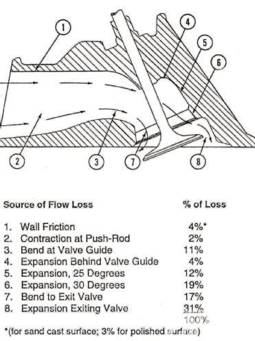 23 Though depicting a generic cylinder head, the increase in flow over stock by reworking a port holds true for a Pontiac engine.
In the next installment, we will perform a preassembly and then final assembly of our stroker 455.