Main Circuits-or a Trip Down Venturi Highway
If there is one part in the world of high performance that everybody knows, it has to be the Holley four-barrel carburetor. The Holley has evolved through hundreds of variations and dozens of popular models, but the basic four-barrel carburetor has changed very little in the last 50 years. This is a great advantage for car crafters because if you're armed with the basics on one carb, that knowledge will carry you through all the different variations. We even have some new stuff for those of you who think you've seen it all.
While everybody thinks they know a lot about carburetors, there's always more to learn about even basic fuel circuits. We'll concentrate on the most important one: the main metering circuit. This circuit is simple when you break it down to its essentials. Let's take a look.
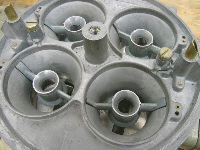
 To give you an idea how booster shape can affect carb sizing, this is a Holley 750-cfm Dominator carb. Note how the diameter of the booster flares at the bottom. This makes the booster more sensitive, reduces the overall area of the venturi, and cuts the rated airflow through the carburetor by 300 cfm.
Fuel enters the float bowl where the height of this reservoir of fuel is regulated by the float that controls the needle and seat. Near the bottom of the bowl is a pair of main metering jets that restrict the amount of fuel that enters the main metering system. After passing through the jets, fuel collects in the main metering well at the same height as the fuel in the bowl. Extending into this main metering well from the top of the metering block is an emulsion tube. This tube is drilled with several holes intersecting the tube at various heights. These holes are used to mix air with fuel. The air is introduced through an air-bleed located at the top of the carburetor usually near the entry to the venturi. This is most often referred to as the high-speed air-bleed. Additional air is mixed with the fuel through emulsion holes in an adjacent air chamber. This air/fuel mix travels across a short passageway and exits from the booster located in the main venturi.
It requires a small amount of force to push fuel literally uphill in this circuit. As air speed increases through the main venturi of a carburetor, it creates an amplified low-pressure area inside the booster venturi. Because atmospheric pressure pushing on the fuel level in the float bowl is greater than at the booster, the pressure difference is enough to push the fuel through all the restrictions and passageways on its way out the booster and into the intake manifold.
The key to a properly designed performance carburetor is to move fuel out of the booster as efficiently as possible while creating the proper air/fuel ratio as the engine runs through its rpm band from just past idle to redline on the tach. This is the job of the main jet, the emulsion holes in the main well, the high-speed air-bleed, and the shape and design of the booster venturi, plus a bunch of other obscure variables. All these components work together to create the fuel curve that helps make horsepower.
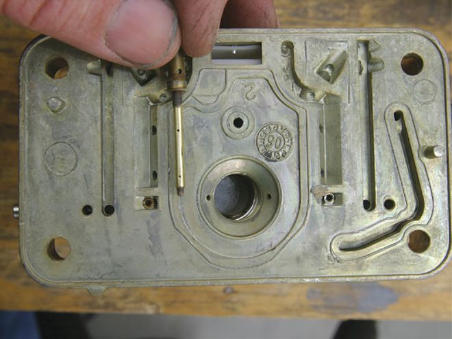 This is an emulsion tube found in most Holley carburetors. This tube sits in the main well and mixes the fuel with air from the air-bleed and adjacent air channel that eventually finds its way to the venturi booster.
Emulsion Immersion
You'll see references here to emulsion circuits, an important-sounding term that describes mixing fuel with air. Think of it as blowing bubbles in the fuel. All carburetors mix air with fuel in the venturi just before it enters the engine. But carburetors also mix air with fuel farther upstream inside the carburetor in the main well to make the liquid fuel easier to manage. Holley carburetors use a parallel air well that transfers air into the main well through two, three, and sometimes five holes that can be seen in the metering block photo (page 36). While this passage is called an air chamber, fuel still resides in this chamber at the same level as the fuel in the float bowl. As fuel demand increases at higher engine speeds, the float level drops, uncovering the lower holes in the emulsion circuit, which adds more air and leans out the air/fuel ratio. Combining the main jet flow area with the area of these emulsion holes and the high-speed air-bleed (along with a raft of other minor inputs) creates the basic fuel curve.
Unless you already know all about Holley metering idiosyncrasies, these emulsion circuits should be left to professional tuners. Just so you know, the basic function follows that increasing the size of these emulsion holes will reduce fuel flow and lean out the overall fuel curve. Increasing the size of the high-speed air-bleed will also delay the onset of fuel flow in the main metering circuit. Reducing the diameter of the high-speed air-bleed produces the opposite effect.
Think of the emulsion tube in the main well as a straw immersed in your favorite soda. A light amount of suction (pressure differential) on a straw with no holes pulls a large amount of liquid very quickly. What's really happening is atmospheric pressure pushes the liquid from the glass into your mouth. If you place a small hole in the straw above the liquid level, this introduces air into the straw, requiring a greater pressure differential (or more time) to move an equal amount of liquid up the straw. The liquid that is pulled up the straw will have tiny air bubbles mixed in with the liquid. What you've created is a simple emulsion tube. The difficulty comes in figuring out the size, number, and placement of emulsion holes in the metering block. The good news is that Holley has worked all this out for you, but at least now you know what those holes do and how important they are to an engine's fuel curve.
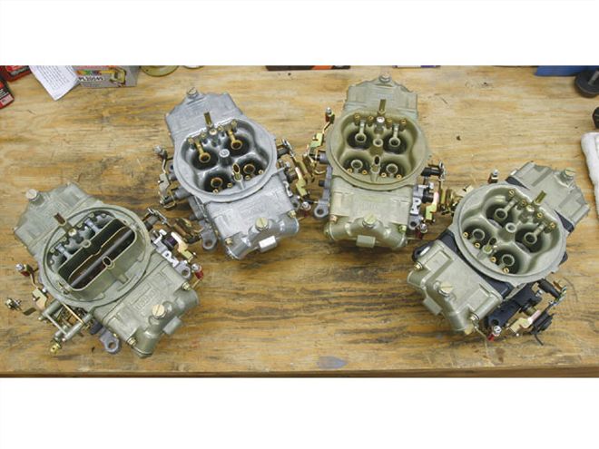 The classic Holley 4150 carb as a mechanical secondary is represented by this 750-cfm carb fitted with a choke housing (far left). The street HP (left) offers a bright finish and the contoured inlet, replaceable idle, and high-speed bleeds available on the standard HP (right) . The HP Ultra (far right) is easily identified by its black billet metering blocks and baseplate.
Holley HP Vs. Street HP Vs. Standard
When the specialty carburetor market exploded with tuners modifying basic mechanical-secondary street carbs for competition, Holley responded with the HP series with a new contoured venturi main body equipped with screw-in air-bleeds, stainless steel throttle blades with buttonhead screws, strengthened metering blocks, and Dominator-style fuel bowls. Following the HP, Holley produced the HP Ultra version, which upgraded to black-anodized billet metering blocks with screw-in idle feed and emulsion jets and a billet baseplate. The HP Ultra is an expensive carburetor, so Holley introduced a much more affordable Street HP 750 in the bright finish in either vacuum-secondary (PN 0-82750) or double-pumper (PN 0-82751) configurations. These carbs offer screw-in air-bleeds and a street/strip calibration that is leaner than the HP and Ultra. The vacuum-secondary 750 Street uses a two-corner idle circuit, while the 750-cfm double-pumper offers a four-corner idle. The original HP carbs are available in sizes ranging from 390 to 1,000 cfm in the 4150 configuration. The HP Ultras come in only 650-, 750-, and 950-cfm sizes. There are also Dominator HP and HP Ultra versions.
Carburetors are required to create a stable air/fuel ratio over an incredibly wide range of rpm and load. HP carburetors come with adjustable air-bleeds and idle feed restrictors that make it much easier to fine-tune the fuel curve to your particular application. By using screw-in idle air-bleeds in the top of the carburetor, you can adjust how quickly the idle circuit responds to changes. By increasing the size of the idle air-bleed, you can slow the response time and slightly lean the idle circuit for very fine adjustments to the idle fuel circuit. The same is true with the high-speed air-bleeds. Generally, working with the fuel side will generate quicker, more measurable results.
The HP Ultra billet metering blocks come with five interchangeable emulsion jets per circuit (making 20 overall for all four barrels) that create an almost limitless tuning arrangement for optimizing the main fuel delivery curve. Tuning these emulsion jets should be left to the experts, but the basic premise is that these emulsion jets introduce air into the main metering circuit. The amount of fuel in the main well is determined by the main jet. But this can be further trimmed throughout the entire fuel-delivery curve (from low engine speed to peak rpm) by adjusting the size of these emulsion holes. Making an emulsion jet larger adds more air and leans out a particular portion of the fuel curve. Conversely, reducing the size of the emulsion jet adds less air and richens the circuit. Air is introduced into successive emulsion holes from top to bottom uncovered as the float level drops during a sustained wide-open-throttle run such as at the dragstrip. From what we can gather from the carb tuners, these are the basics, but the circuits do not always respond in simplistic terms. Before the days of adjustable emulsion holes, this type of tuning required permanent modifications to the metering block. The beauty of aftermarket adjustable metering blocks is that the emulsion holes can now be easily tuned by replacing tiny jets. And if you get lost, you can always return to the original emulsion package and start over.
Circuits
There are more pathways for fuel through the carburetor than just the main metering circuit, so this is your opportunity to become the neighborhood Holley guru. All it takes is a little bit of study. The layout for HP carburetor metering blocks and Dominator carbs will look slightly different from this standard Holley two-circuit metering block, but most of the circuits are exactly the same.
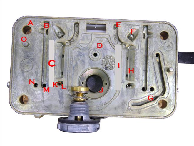
(B) Idle downleg:
This passageway feeds fuel to both the idle discharge port and the idle transfer slot.
(C) Idle well:
Fuel from this well travels to the top of the metering block, then turns 180 degrees and mixes with air from the idle air-bleed into the circuit.
(D) Accelerator pump passage:
This transfers fuel from the accelerator pump to the outlet nozzle.
(E) High-speed air-bleed:
Air from the high-speed bleed enters the metering block here to be mixed with the fuel as it climbs the emulsion tube.
(F) Passage to booster:
This channel transfers fuel from the main well to the booster
(G) Ported vacuum passage:
This connects the ported vacuum source in the throttle body to the outlet where this can be routed to a source like vacuum advance.
(H) Parallel air well:
Air is introduced into the main well through these two holes.
(I) Main well:
Fuel collects here after passing through the main jet.
(J) Power valve channel:
This is where the power valve is located. The two small holes are the power valve channel restrictors (PVCR) that determine the amount of fuel added to the main metering circuit when the power valve opens. This valve determines when additional fuel is added to the main circuit.
(K) Idle restrictor channel:
Fuel from the main circuit passes through this short channel and through a small brass restrictor (L) that acts as the idle circuit jet.
(M) Idle transfer slot discharge:
Idle fuel exits the metering block to deliver fuel to the transfer slot.
(N) Idle fuel discharge port:
Idle fuel exits the metering block and enters the carburetor main body for carb idle fuel below the throttle blades.
(O) Dowel pin:
Two pins locate the metering block on the carburetor main body.
The HP Ultra billet metering blocks come with five interchangeable emulsion jets per circuit (making 20 overall for all four barrels) that create an almost limitless tuning arrangement for optimizing the main fuel delivery curve. Tuning these emulsion jets should be left to the experts, but the basic premise is that these emulsion jets introduce air into the main metering circuit. The amount of fuel in the main well is determined by the main jet. But this can be further trimmed throughout the entire fuel-delivery curve (from low engine speed to peak rpm) by adjusting the size of these emulsion holes. Making an emulsion jet larger adds more air and leans out a particular portion of the fuel curve. Conversely, reducing the size of the emulsion jet adds less air and richens the circuit. Air is introduced into successive emulsion holes from top to bottom uncovered as the float level drops during a sustained wide-open-throttle run such as at the dragstrip. From what we can gather from the carb tuners, these are the basics, but the circuits do not always respond in simplistic terms. Before the days of adjustable emulsion holes, this type of tuning required permanent modifications to the metering block. The beauty of aftermarket adjustable metering blocks is that the emulsion holes can now be easily tuned by replacing tiny jets. And if you get lost, you can always return to the original emulsion package and start over.
Blow-Through Carbs
When centrifugal superchargers really began to push major air a few years ago, the demand for blow-through carburetors matched the demand for blowers. Regardless of what you might have heard, it takes serious modifications to create a good blow-through carb. Because of the massive amount of compressed air that the blower moves for a high-horsepower combination, the carburetor has to meter a bunch of fuel. While a standard Holley downleg booster carburetor will work, the most popular and successful blow-through carbs use annular discharge boosters. These boosters flow more fuel for the same signal and introduce the fuel into the engine in a more atomized form to make more power.
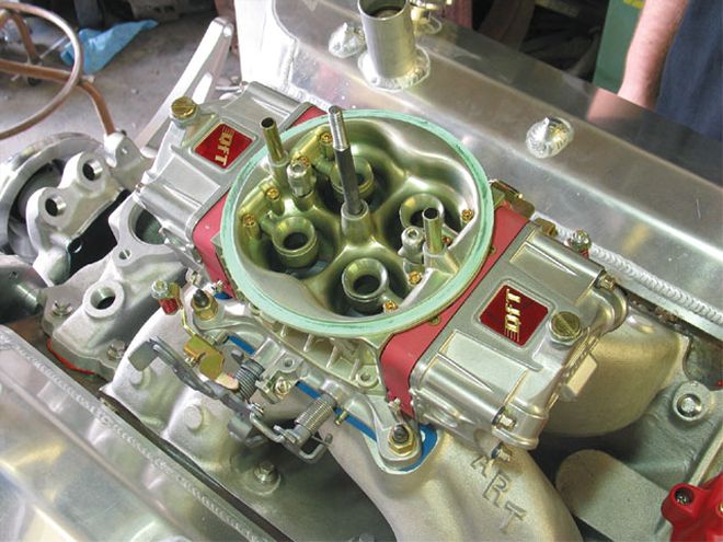 Blow-through carburetors like this Quick Fuel 750 use annular-discharge boosters to deliver a greater volume of fuel to maintain a safe air/fuel ratio at full power. Dropleg booster carbs can be made to work at wide-open throttle but often tend to be pig rich at part throttle when not under boost.
But there's more to this than just using an annular-booster-equipped carburetor. According to Quick Fuel Technology's Marv Benoit, increasing the main well capacity of the metering block and using smaller emulsion holes increase the volume of fuel. Quick Fuel also increases the diameter of the passage leading to the booster in an effort to feed more fuel. This approach even extends to the carburetor bowls. With low-boost combinations under 10 psi, a stock Holley needle-and-seat assembly is sufficient. However, with the mondo blower packages capable of moving and pressurizing huge volumes of air, just delivering enough fuel through a single four-barrel carburetor becomes an issue. Benoit says he replaces the typical 0.110-inch-diameter needle and seat with as large as a 0.150-inch assembly that radically increases the volume of fuel delivery. This also requires attention to the fuel-delivery system because excessive fuel pressure can do more harm than good by aerating the fuel in the bowl.
The next step in this direction is dual-needle-and-seat float bowls, such as the C&S Super Bowl, that are appearing on some of the more radical blow-through carbureted applications. We saw this idea on two engines in the DynoMax shootout last year fueled with E85. One of the first to champion this idea many years ago was McClintic Racing from Albuquerque, New Mexico. Expect to see several versions of these dual-float-bowl designs in the near future. Benoit says he thinks that adequate fuel delivery is critical on any engine making 500 hp or more and especially important on a blow-through application.
Another selection tip is to undersize the carburetor slightly. As an example, Car Craft tested a 540ci big-block Chevy on the dyno with a blow-through F2 ProCharger in the Oct. '05 issue ("Blow-Through Superchargers"), making a repeatable 976 hp on pump gas with what most enthusiasts would consider a too-small 750-cfm annular-discharge Quick Fuel carburetor. While power was limited with the factory iron heads, the carb and fuel-delivery system performed flawlessly.
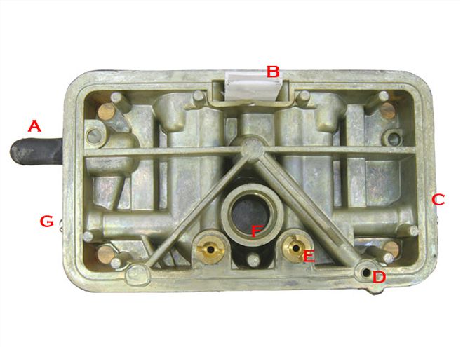
Bowl Side of Metering Block
(A) Timed spark port:
This outlet supplies ported manifold vacuum for distributor vacuum advance only after the throttle is opened slightly.
(B) Vent whistle:
This plastic vent piece vents the float bowl area and also prevents fuel from splashing into the primary venturi under hard acceleration.
(C) Idle mixture screw:
This adjuster screw meters the amount of fuel and emulsified air delivered to the engine at idle.
(D) Accelerator pump entry point:
This is where the fuel from the accelerator pump enters the metering block, traveling up that adjacent diagonal port to the center hole on the opposite side of the metering block.(E) Main jets:
These are the replaceable main jets used to trim the main metering system.
(F) Power valve:
Fuel enters the power valve enrichment circuit from the float bowl.
(G) Other idle mixture screw:
This adjuster screw meters the amount of fuel and emulsified air delivered to the engine at idle.
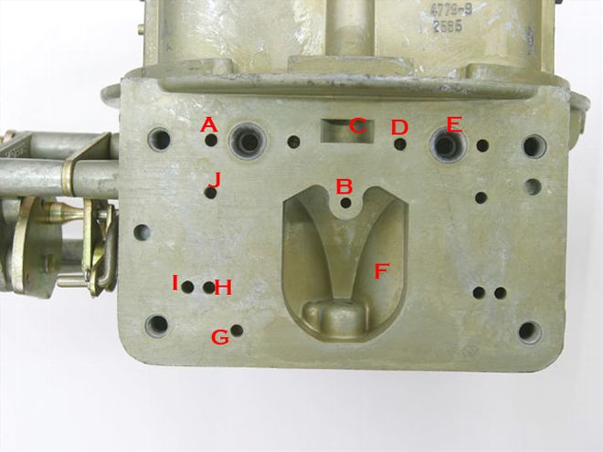
Carb Main Body
(A) Idle air passage:
Air from the idle air-bleed enters the metering block here.
(B) Accelerator pump discharge passage:
Fuel from the accelerator pump enters the main body of the carb here and travels up to the squirter.
(C) Fuel bowl vent:
This vent places atmospheric pressure on the fuel in the float bowl.
(D) High-speed air-bleed passage:
This is where air from the high-speed air-bleed enters the metering block.
(E) Booster venturi inlet: Emulsified fuel from the main well enters the booster through this passage.
(F) Power valve vacuum well:
Intake manifold vacuum is present in this cavity. When the throttles are opened and vacuum drops off in this well, the power valve opens.
(G) Timed spark port:
This hole delivers manifold vacuum only after the throttle is opened past curb idle. This is normally the outlet port for vacuum advance.
(H) Idle transfer slot to discharge:
This port delivers fuel to the idle transfer slot in the throttle body that is uncovered under light throttle.
(I) To curb idle:
Idle fuel enters here from the metering block to the curb idle discharge point on the throttle body.
(J) Auxiliary air:
This hole is used only with an auxiliary idle air-bleed circuit.
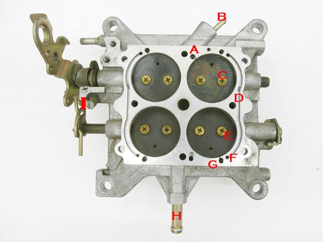
Throttle Body
(A) Power valve vacuum port:
This connects the manifold vacuum to the power valve. This is also where newer Holley carbs are fitted with a blowout protection check ball to protect the power valve.
(B) Full manifold vacuum source:
Outlets for constant manifold vacuum.
(C) Primary throttle blades:
All air flows through these blades at part throttle up to a given percentage of throttle opening.
(D) Curb idle speed screw:
This sets the idle speed on the primary side.
(E) Secondary throttle blades:
Controlled by either mechan-ical or vacuum actuation.
(F) Secondary throttle stop:
Small adjustment screw that is a stop for the secondary throttle blades.
(G) Curb idle transfer passage:
Machine passage for idle fuel discharge to secondary side with two-port idle mixture screws for more even idle fuel entry into engine.
(H) Idle transfer slot:
This is where idle fuel enters as the primary throttle blades are opened for part-throttle operation.
(I) Full manifold vacuum source:
Outlets for constant manifold vacuum.
(J) Curb idle discharge:
This passage leads to the small hole underneath the throttle blades where the idle fuel enters the engine.
Setting Idle Speed
The problem with a long-duration camshaft with lots of overlap is low manifold vacuum that requires more throttle opening to set the proper idle speed. The ideal position of the throttle blades in relation to the idle transfer slot is shown in Photo A where the primary throttle blades just barely uncover the bottom of the transfer slot-roughly about 0.020 inch. However, long-duration camshafts often demand much more throttle opening as shown in Photo B. This uncovers too much of the idle transfer slot (arrow), delivering more fuel from the idle circuit. This creates an off-idle hesitation or bog that is difficult to eliminate.If the curb idle speed position of the primary throttle blades on your Douglas Glad signature monster-cammed engine looks like Photo B, the quick fix is to drill two small holes in the primary throttle blades adjacent to the transfer slot. Start with holes of roughly 1/16 inch in diameter and then readjust the idle speed on the carb. Adjust the hole size, idle speed, and throttle-blade position until you achieve a blade location similar to that in Photo A.