In 20 years, the hydraulic roller lifter has gone from a hot rodding oddity, to plain vanilla common fare. In those 20 years, one aspect that's changed very little is the rpm capability of the basic hydraulic roller. Sure, there are some moves to get a hydraulic roller valvetrain to live at 7,500, but they are steps that mostly remove the hydraulic self-adjusting aspect of the lifter. The problem with a typical hydraulic roller is that it tends to collapse when the loads (either from the valvespring or from rpm) get above a certain level. Just when this happens depends on the hydraulic plunger's fit in the body. The closer the fit, the higher the rpm the lifter will go.
Allowing the weak link in the chain always dictates the overall result: the valvetrain's rpm limit is dictated by the softest lifter. There are two common ways to get around this problem so higher rpm can be reached. First, adjust the hydraulic stroke of the plunger to within a few thousandths of bottoming out, and second, make a spacer that limits the lifter plunger travel to about 0.010 inch. Both of these moves for a street machine could mean you now have to periodically adjust the valvetrain as per a solid lifter. This is not good if it involves removing the air conditioning pump, an intake manifold, and a whole load of other plumbing components. A principle point of a hydraulic valvetrain is that it should not only be quiet, but also service free. So how do we push the envelope in terms of rpm while retaining the standard quarter-turn on the adjustment? That's just what we've set out to show here.
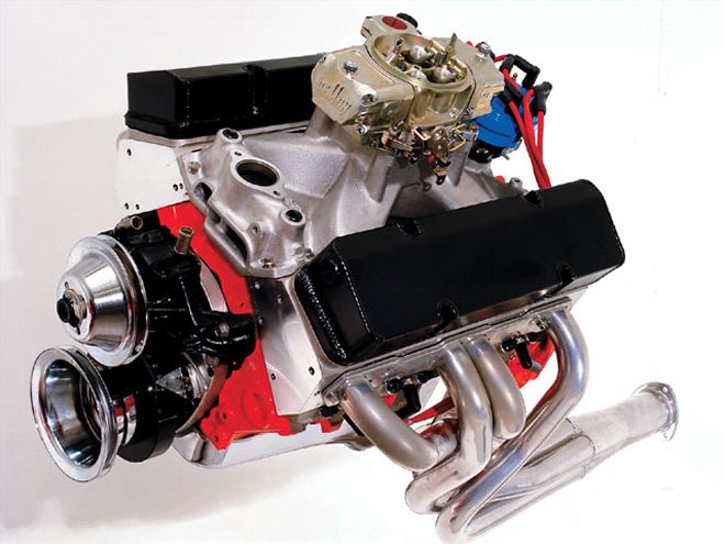 Here is our test engine, which sports a Scat 3.75-inch crank to make 383 inches.
Before delving into details, we need to establish where we are in terms of rpm, and why we need to go further, even for strictly street-driven machines. At present, a typical OE roller lifter is good between 5,800 and 6,000 rpm. Sure, you may see revs above these figures, but either the element of luck or a mild stock cam are involved. If the goal is serious power, neither of these factors can be relied on to get the job done. The popularity of stroker motors and the availability of killer cylinder heads mean a valvetrain with both high lift and rpm capability is now a prime requirement.
The Test Engine
In the last 12 months, a lot of cylinder head testing has come my way. These have been heads that have enough flow to push peak power rpm levels-even in big-inch stroker motors-well past the hydraulic roller's 5,800-rpm limit. Couple this with cam profiles such as COMP's super aggressive Xtreme series, which has really strong performance in big-inch motors, and you can see there is a real need for high rpm and high valve lift.
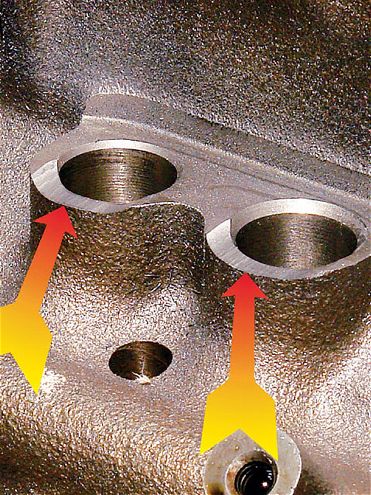 To allow the Pro Magnum lifters' link bar to clear the block, the lifter bosses need to be cut as shown here by the arrows.
Probably the number one inspiration to run the tests for this feature came from Air Flow Research. The guys at AFR have been cognizant of the need for more rpm from a hydraulic-roller-equipped engine for a good number of years, and have taken numerous steps to achieve such. For instance, their CNC-ported small-block Chevy heads sport lightweight valves with 8mm stems and a small-diameter high-tech valvespring and retainer that further cuts mass by 20 percent. All this is very hydraulic-roller-friendly stuff, and experience with such has shown it pays handsome dividends. But what if you don't have a set of AFR heads? As it happens, AFR still has a fix.
Our test engine, which was loaned to us by T and L Engines, fits the format. It's a 350 with a Scat 3.75-inch stroke crank that, with a .030-over bore, delivered 383 inches. The heads for this engine were Dart Platinum 215cc heads, which have more than enough flow to put peak power rpm at or above 6,500, even for a street driver. We had a target of 530 hp, and with a 11.5:1 compression ratio, the engine should, with the right cam, peak at about 6,200 and have an optimal shift point around 6,600 rpm. Here's the valvetrain that went together for this project.
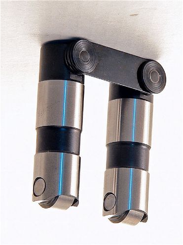 We elected to use the COMP Pro Magnum link-bar lifter-instead of the stock "dog bone" type lifter-because of its superior capabilities.
Valvetrain Specs
Our cam needs to deliver a healthy amount of lift-we figure about .600 inch is sufficient to deliver enough flow while remaining within realistic mechanical limits. As for duration, something longer than what is normally required in a 350 should be used, as the larger displacement makes the cam act as if it is shorter. To cover the needs of this engine, a custom single-pattern cam having an Xtreme Energy (PN 3317) was chosen. This has 293 degrees of "off-the-seat" duration, and 242 degrees at .050 lift. With a 1.65 rocker setup, this puts the lift close to the .600-inch target. The lobes were ground on the shaft with a 106-degree lobe centerline angle, four degrees advanced.
The block is a late model, which comes from the factory with hydraulic rollers. The OE lifters, though, are the "dog bone" retainer type. These are not the best option. The OE rollers were replaced with COMP's Pro Magnum link-bar-style lifter (PN 885-16), similar to those seen in "The Twister: Part 3" that's found in this issue. On previous occasions, these have consistently turned to 6,000 rpm, which is better than stock, however they are not a straight replacement for the dog-bone-style OE lifter. To make them usable in the late-model roller-lifter block, some clearancing needs to be done on the lifter boss, which is higher than on earlier flat-tappet blocks.
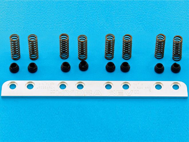 AFR's hydraulic roller lifter Rev Kit allows better lifter control by applying spring force to the lifter body instead of the hydraulic plunger.
The next components in the valvetrain constitute the principle point of our test. Namely, the Air Flow Research hydraulic roller Rev Kit. This locates, via an adaptor, a spring on the body of the roller lifter. This spring does all the work as far as keeping the lifter in contact with the cam profile. By having the spring press on the body instead of the plunger, the lifter is controlled without any chance of hydraulic collapse. This means the valvespring has less overall mass to control, so it can be lightened up. This also reduces the probability of the lifter collapsing. It all sounds simple enough, but does it really make a significant difference? As we go further, you'll realize all the components in the valvetrain are being selected because they are among the best functioning parts available. This means the system, prior to the installation of the Rev Kit, is about as good as it gets, and leaves the lifter collapse as the Achilles' heel of the system.
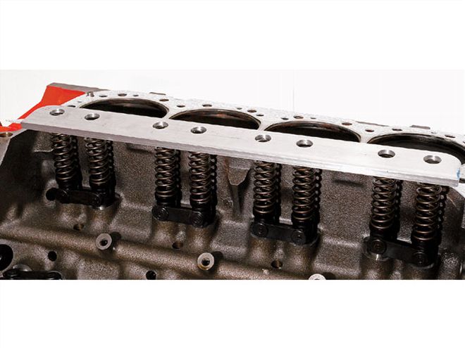 Here is the Rev Kit's assembly prior to installing the heads. Once the heads are on, the system is trapped in place.
A set of COMP hi-tech pushrods were used. Some advice here on pushrod selection might help solve a possible valvetrain problem. The stock pushrod, in conjunction with a stock valvespring, can go into a mild lateral resonance. This causes it to momentarily unseat from the lifter and rocker. The lifter then expands to take up the clearance, and subsequently holds the valve momentarily off the seat. The result? A loss of power from the reduction in cylinder pressure. When this happens, it isn't really apparent, but fixing the problem with a stiffer, higher-frequency pushrod (as we are doing here) can result in a 5hp increase.
What we're using in the rocker department is a little different from the norm. For some time, we've wanted to try Crane's shaft rockers with the ceramic/poly plain bearings. We have had several engine builders tell us they work well in terms of power, and also seem to run quieter. Along with that, Crane is also conservative on the stated ratio, and usually its rockers will lift the valves as much as .025 inch higher than the ratio quoted. With a 1.6 rocker, our test engine's intake valve should lift to .576 inch. What was needed here was a lift as close to .600 inch as possible. The engine needs this much valve lift, and doing so also put our COMP beehive valvesprings (PN 26918) in a near-optimal range for best valve control. A few words about this spring before we move on. This spring is the latest iteration of this part number. With its ovate cross section and beehive form, it has the capability to deliver a lot of rpm without excessive spring loads on the valvetrain. Compared to a comparable conventional spring with the same spring seat and over-the-nose pressure, it delivers (so long as the lifters don't collapse) about a 1,000 rpm more before it loses control. Along with a much smaller and lighter retainer, it makes for a dynamically sound hydraulic valvetrain. Normally, these springs are set up to deliver 130 lbs on the seat, but because they no longer have to control the lifter mass (our Rev Kit is doing that), they were set up to give 110 lbs on the seat.
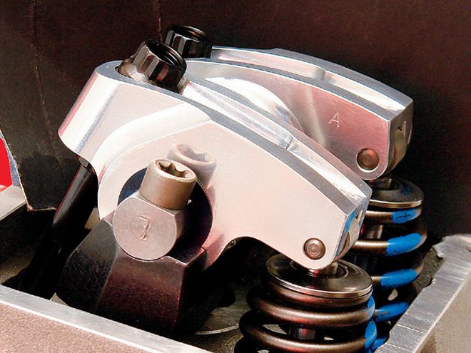
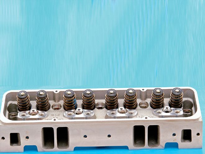
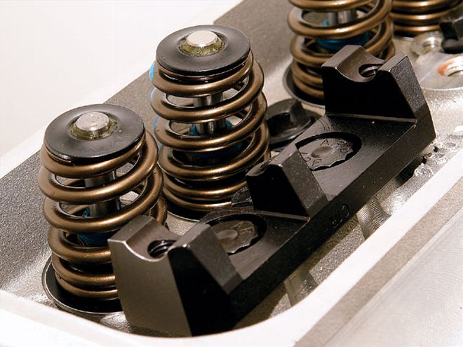 Two things to note: the COMP beehive springs with their small retainers, and the base of the Crane shaft rocker setup.
Cylinder Heads and Intake
Normally for a 383 street driver we would use heads with a 200cc port volume, but in this case, top-end output with a relatively big cam was the primary consideration. This prompted the use of a set of Dart's Platinum 215cc runner heads. With strong flow curves right out of the box, these heads have what it takes to allow a 383 to usefully turn as much as 7,000 rpm-if the valvetrain allows it.
For an intake manifold, an Edelbrock Victor Jr. with a built-in 1-inch spacer (PN 2999) was used. This, together with an 850 Barry Grant vacuum secondary Demon carb, rounded out the induction system.
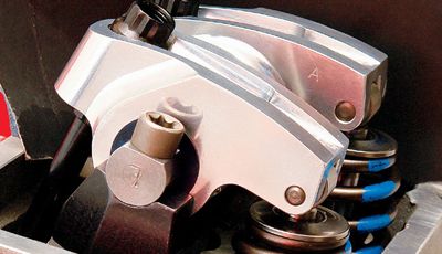
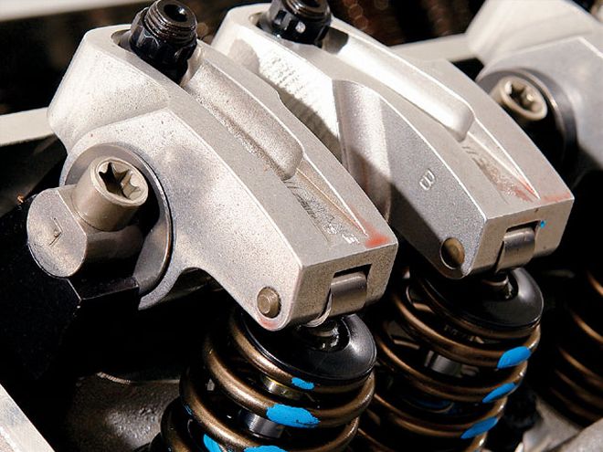 Here is the completed Crane shaft rocker setup. These rockers deliver a net valve lift of over .590 inch on our test engine.
Ignition
The ignition system is a little different than the norm. Instead of a regular distributor, a Crane "all-electronic" unit was used. Some testing a while back showed the unit to be a very functional item with the convenience of adjustability not possessed by a regular distributor. The built-in timing curve module has nine rpm-related computer-controlled mechanical-advance curves, and these are supplemented by three vacuum-advance curves. Having such a range to choose from is going to allow the timing curves for part-throttle cruise to be optimally set. What this does is allow us to set up the low-speed and idle parameters so that the negative effects of a relatively big cam are somewhat held in check. Just to give an up-front idea of what this was worth, the engine's minimum idle speed without the aid of vacuum advance was a lopey 900 rpm. With the vacuum, it was 780 rpm, with only about half the lope. Also worth noting is that the amount of fuel used at idle with the vacuum advance is about 30 percent less than without.
To complete the ignition system, we used a Crane HI-6 multiple spark ignition box and the appropriate hi-output coil. The last item on the list is to plumb in the plug cable harness. The "down under" routing was used in case we had to make multiple visits to the rockers for adjustments, should we fail to reach our target rpm by the regular quarter-turn valve adjustment.
 The 215cc runner Dart Pro 1 Platinum heads deliver strong flow right through the lift range, right up to the targeted .600-inch valve lift.
Test Time!
At this point, we were ready the take the engine over to T and L Engines for the dyno test. Using T and L's Innovate wide-band fuel mixture data acquisition system, carburetion was dialed in after a few exploratory pulls. Getting the best rpm and vacuum advance curves for the job was even quicker, courtesy of Crane's all-electronic distributor. All the pre-test setup work was done with an upper rpm limit set to 5,700, which is just below the accepted limit for a typical stock hydraulic roller valvetrain.
Before looking at results, let's restate our goals. First, we assembled a valvetrain with typically .050 inch more lift than normal for a 6,000 rpm valvetrain. Second, by targeting 6,600 rpm, we are attempting to get the valvetrain to turn to some 600 to 800 rpm more. Third, we hoped getting those extra rpm would be instrumental in achieving a target output of 530 hp.
The first dyno pull with the upper rpm limit at 6,500 showed we had already exceeded our target power with 531 hp at 6,300 rpm. For the next pull, the upper limit was set at 6,600 rpm, but the system refused to go 20 rpm above the 6,500 point. At 6,500, the valvetrain appeared to be totally under control, yet 20 rpm later it was in complete disarray. But we did have another card up the old sleeve. Extensive testing showed that Mobil 1 was among the best off-the-shelf oils when it came to fending off lifter collapse. Armed with the knowledge that some oils can leak faster than others and thereby greatly affect where lifter collapse starts, we switched our traditional mineral-based oil over to Mobil 1 synthetic. After bringing up the motor to temperature, some runs were made. Nothing changed until about 5,800 rpm, where power started to look better. Peak power at 6,300 went up by 4 hp, and at 6,500, it rose by 7 hp. That was all good, but the valvetrain crash threshold did not appear to change-everything still came unglued at 6,520! The nearby chart shows our final test results to the nearest whole number.
Conclusions
Although all the parts of the valvetrain played a significant role toward making the power, it has to be said that a solid 500 rpm of the 6,500 rpm seen was achieved by the use of the AFR Rev Kit. By adopting this, we were able to make the most of the power producing capabilities of COMP's Xtreme cam and the Crane high-lift shaft rockers. After running all our tests, we tore the engine down to check that nothing had been hurt.