One of the worst experiences in the world has to be spending all the time and money required to build a new race engine only to spin a bearing or have some other problem develop before it has even completed the break-in process. Building your own race engines can save you a lot of money (not to mention giving you the pride that comes from beating the competition with your own stuff), but race engines are too expensive for learning by trial and error.
Fortunately, many of the reasons for early engine failure are avoidable. All that is required is patience, attention to detail, and a few measurement tools that will help make your life a lot easier. In this article, we will describe how to properly install a crank into a properly machined block. This is the first and one of the most critical steps because everything-even the valvetrain-connects in some way to the crankshaft.
The most important part of installing a crank is making sure you have the proper clearance between the main bearings and the crank journals. The general rule of thumb is 0.001 inch of clearance between the bearing and journal for every inch of journal thickness. For a Ford Windsor with 3.00-inch mains, that works out to 0.003 inch of bearing clearance.
The first thing to do is to throw away the Plastigauge. Yes, it is simple and inexpensive, but it also isn't reliable enough. The Plastigauge may be OK for a quickie stock rebuild for your grandmother's station wagon, but it isn't accurate enough for racing. Instead, invest in a dial bore gauge and a couple of micrometers that can measure accurately to at least 0.001 inch. We sourced our mics for this project from Powerhouse Products. You can spend more on ultra-high-end measurement tools, but you can get a pair of quality micrometers (one that measures between 2 and 3 inches and a second that measures from 3 to 4 inches) along with a dial bore gauge for less than $200.
Now follow along as we build the proper foundation.
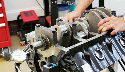
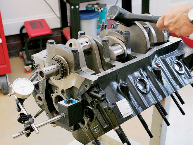
This Ford block may look like it's ready for the crank to be dropped in, but taking a few extra minutes to make some critical measurements can make the difference between a race-winning engine and one that doesn't make it through the break-in process.
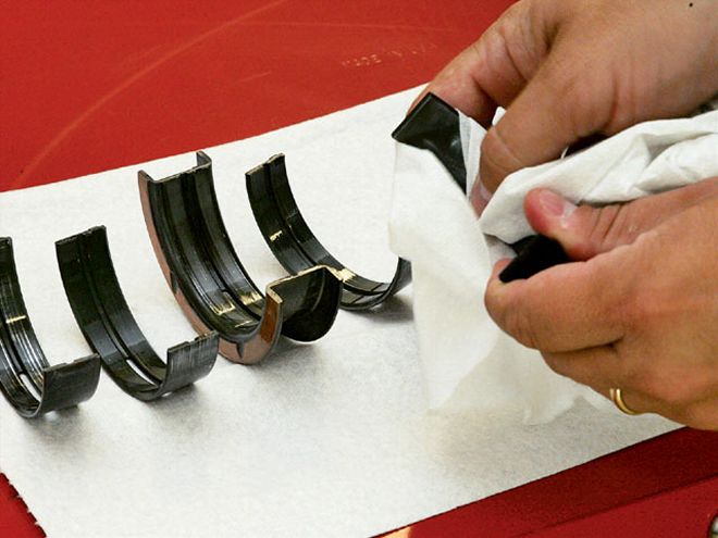
Any contaminants, including dirt or small bits of metal trapped between the back of the bearing and the main housing bore, can change the bearing clearance. Although everything may look clean, be sure to wipe down both the main housing bores as well as both sides of the bearings with a lint-free rag and some lacquer thinner before installing the bearings.
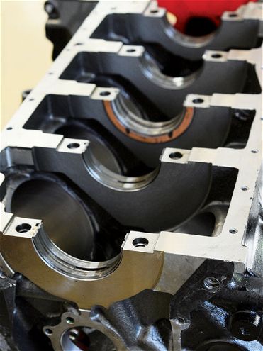
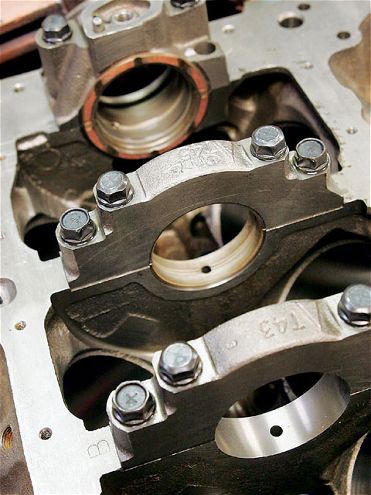
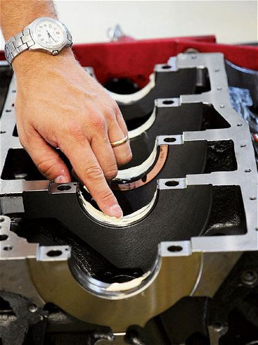
All traditional V-8 engines have a thrust bearing to limit crankshaft endplay (movement forward and back). On a Ford, it is in the third main cap, as you can see here.
Here's a shot of a Chevy block. The thrust bearing is located in the rear main cap. Basically, the position is the only difference here. They both work much the same way.
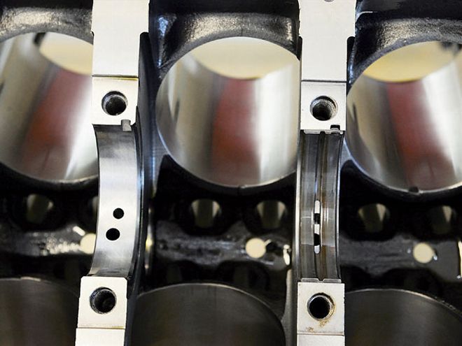
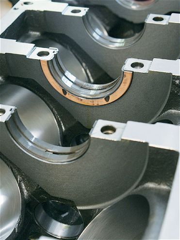
For both Fords and Chevys, the upper bearing shell (shown here) lays into the block and has an oiling hole as well as a groove to help oil the entire journal surface. The lower shell is smooth and fits into the cap itself. Notice how the shell has a tang that only allows it to fit into the block one way. This also helps lock the bearing in place once the cap is bolted into position and keeps the bearing from spinning.
Next, fit the lower bearing shells into the caps. The caps should be marked with numbers and an arrow indicating proper position and direction. The cap in the front of the block is always number one, and the arrows always point toward the front. The caps should be a tight fit into their registers in the block. You can use a dead-blow hammer to gently tap them into position. Never use the main cap bolts to pull the caps into place. This can damage the threads in the block.
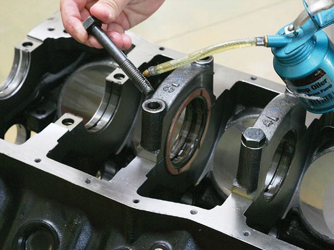
Before threading the cap bolts into place, lubricate both the threads and the underside of the cap with motor oil. This will produce more consistent torque results.
A Ford Windsor uses half-inch bolts, which means they should be torqued between 95 and 105 lb-ft. Torque the bolts in threeapproximately equal steps (35, 70, and 95 lb-ft), alternating sides of the cap at each step instead of pulling the bolts directly to the final torque setting.
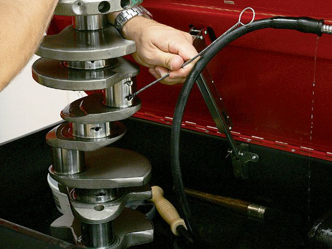
If you haven't already done it, take a moment to make sure the crank is completely clean. Use a brush to eliminate metal shavings hiding inside the oiling holes, and then wipe down all the journals.
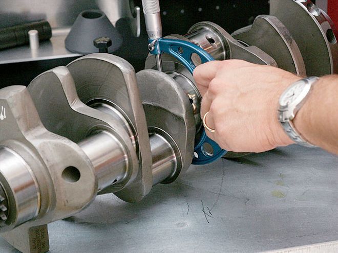
Using a micrometer, measure one crank journal. On this Windsor crank, the journal size was dead on at 3.00 inches. Lock the micrometer down so that it won't move.
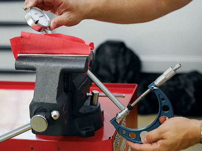
Next, calibrate your dial bore gauge. The easiest method is to gently hold it in place in a vise. Place the micrometer (still locked to the size of the crank journal you just measured) over the dial indicator and zero out the gauge. Now use the dial bore gauge in the corresponding housing bore for that journal. It should read approximately 0.003 inch larger. Of course, it rarely will be perfect. On a Ford with a 3.00-inch journal, your working range can be between 0.0015 and 0.0047 inch. On a Chevrolet with a standard 2.448 journal, you should hold your clearances between 0.0015 and 0.0027 inch. If you find your bearing clearances outside that range, you can purchase a set of bearings that are either oversized or undersized by 0.001 inch. By mixing standard and under- or oversized shells, you can change your bearing clearance by 0.0005-inch increments. When you do this, make sure to keep all the shells of one type in the same location. For example, if you use one standard shell and one undersized shell, keep all the standard shells in the cap and all the undersized shells in the block, or vice versa. The location isn't important as long as you are consistent.
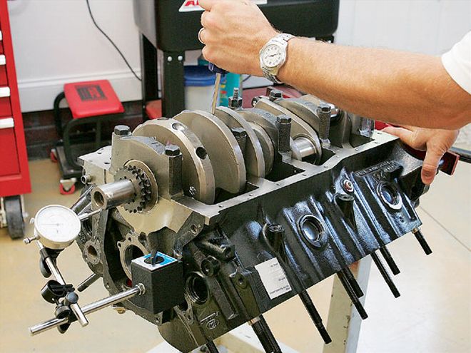
Once you have measured all your journals and matched them to their specific bearings, you are ready to lay the crank in place. Before doing that, however, spread a coat of assembly grease on the bearings to protect the crank. Do not lubricate the thrust faces of the thrust bearing at this point.
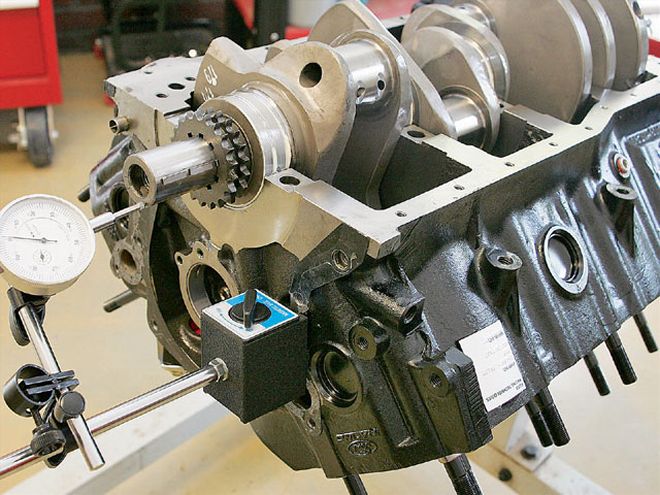
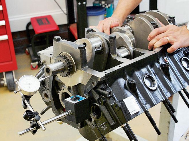
Now lay the crank into position. Without installing any of the caps, use a dial indicator on the nose of the crank to measure endplay. You should be able to move the crank back and forth by hand. Crankshaft endplay for both Fords and Chevys should be between 0.004 and 0.009 inch.
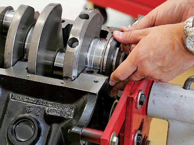
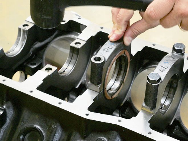
If you have the correct amount of endplay, go ahead and install the rear main seal before bolting on the main cap.
The next step is to bolt up and torque all the main caps (don't forget to oil the bolt threads) except for the cap containing the thrust bearing. Check your endplay again. If you don't have enough play, one of the caps is out of alignment. You can adjust the cap location slightly by tapping it lightly with a dead-blow hammer and then tightening the bolts back down.
Again, if the endplay is correct, you can install the last main cap-this one with the thrust bearing. Tap it into place but do not torque the cap bolts. Instead, rap the crank lightly, either forward or back, to align the thrust faces of the two bearing shells. Now tighten the bolts to the proper torque specs.
Once you have reached this point, you likely will notice the endplay has tightened up a bit. You can use a screwdriver placed between one of the main caps and a counterweight to help you move the crank. Do not use excessive force.
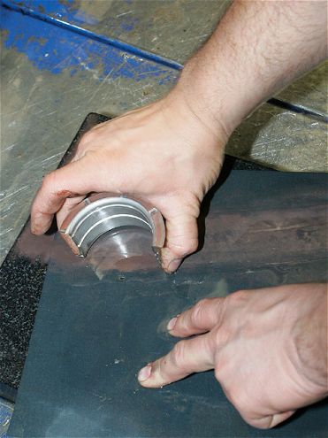
If there isn't enough endplay, you may need to reduce the thickness of the thrust face of the thrust bearing slightly. This can usually get you a thousandth or so. Lightly rub both faces of both halves of the thrust bearing on super-fine sandpaper that is being lubricated by a constant stream of fluid in your cleaning tank. It's also a good idea to use a surface block (or even a pane of glass) underneath the sandpaper to make sure you are sanding on an even plane. Remember, there's no way to tighten up a crank with too much endplay. That's usually a sign of too little fillet cut into the crank.