'The biggest challenge to degreeing a camshaft is convincing yourself to do the work instead of just lining up the dots on the cam and crank gears and calling it a day. While degreeing a cam rarely makes more power, it's one of those things you should do on any good performance engine. Does your daily driver need the cam degreed? Probably not, but if nothing else, it's a great skill to learn, especially if none of your buddies knows how it's done. As soon as you have the skill, you will instantly become the neighborhood cam guru. And that's not all bad. As the man once said-knowledge is power.
The Tools
There are only a few specialty tools you'll need to accurately degree a cam. The essentials are a degree wheel, a magnetic base and dial indicator, a pointer, a piston stop, and a secure way to rotate the engine. You can make your own pointer and piston stop, so that leaves investing in the dial indicator and base, since degree wheels are so inexpensive as to be inconsequential. If nothing else, a degree wheel looks good in your toolbox. If you bought them individually, you could get a 9-inch degree wheel, a dial indicator, and a magnetic base through Powerhouse for around $75. Add a crank nut to turn the engine over, and you're in with everything you need for less than $100.
We need a magnetic base and dial indicator to read the cam lobe lift, while the crank nut is necessary to turn the engine over both forward and backward without touching the degree wheel. The only difficulty with the budget degree wheel is that it's designed to be used with the professional crankshaft turn socket, which is a great tool that only costs $11 more than the crank nut. The point of either crank tool is the ability to rotate the engine in either direction without disturbing the position of the degree wheel. Move or bump the degree wheel, and you have to re-establish TDC.
We didn't include the price of a piston stop because for jobs where the heads are off the engine, you can make one out of a steel plate with a couple of holes drilled. For degreeing with the heads on, you can make a piston stop out of an old spark plug. Or, you can purchase these tools already made for a reasonable price. We added a few other handy tools to our tool list that are great to have, such as a cam handle for installing camshafts. These are great time-savers if you plan on building lots of engines.
Finding TDC
No, we're not talking about The Discovery Channel-TDC stands for top dead center. All the work in degreeing a camshaft revolves around an absolutely accurate position of TDC on the degree wheel. That's where we'll start.
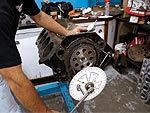
With the cam, crank, timing set, and No. 1 piston and rod in place in the engine, the first thing to do is mount the crank nut on the crank snout, install the degree wheel, and position a pointer so it's very close to the degree wheel and lines up directly over an individual timing mark. There should be no question where it is pointing. This eliminates visual errors.
Next, rotate the crank until the No. 1 piston is close to TDC. Adjust the degree wheel to indicate TDC. This just has to be close. Now turn the crank about 50 degrees counterclockwise and mount your piston stop. For our Rat, we used a dial indicator on a bridge, but it works the same way. For a piston stop, merely rotate the engine clockwise until the piston contacts the stop and record the number on the degree wheel. Then rotate the engine the opposite direction until it hits the stop and record that number. If the degree wheel is located correctly (which it probably isn't), the numbers on either side of TDC will be exactly the same-let's use 24 degrees for our example (your number will vary). Most often, you'll get two different readings-say 26 and 22 degrees. Add the two numbers and divide by two, which in this case will be 26 + 22 = 48 / 2 = 24 degrees. Move the degree wheel to read 24 degrees against the stop and then rotate the engine back to the stop on the opposite side of TDC. It should read the same number.
This first step is the most important. If the TDC position is not correct, nothing else you measure will be accurate. Double-check your work up to this point. Once you have accurately established TDC, you can move on to actually degreeing the camshaft.
Get Your Degree
The next step is reading cam lift with a dial indicator. First, you'll need to position the magnetic base to the block and then mount the dial indicator. Next, you'll need a tappet of the same style as the cam. You can't use a roller tappet on a flat-tappet cam nor can you use a flat-tappet lifter on a roller cam.
Our cam for the fat Rat is a mechanical roller, but the procedure is always the same regardless of cam style. Do not place the tip of the dial indicator in the pushrod cup of the lifter to read lift. The lifter cup radius offers no flat area for repeatability. Instead, use the edge of the lifter or build a dedicated lifter with a flat that will accurately locate the dial-indicator plunger. Make sure the dial indicator travels roughly the same angle as the lifter. If the heads are bolted on the engine, you can use a pushrod to move the dial indicator
Once the dial indicator is set, run through the entire lift curve several times to ensure it always returns to zero. If it does not, this is usually due to binding between the lifter and the dial-indicator plunger. Reposition the dial indicator until the indicator always returns to zero. This is important for the accuracy of your test.
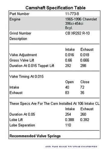
Now we need to talk about the timing card. In our case, we were degreeing a Comp mechanical roller cam. Comp's cam cards for mechanical roller cams list the opening and closing specs at 0.015 inch. Because these numbers are close to the base circle, it's difficult to create accurate measurements. This is why Comp prefers to degree cams by using the intake-centerline method. That procedure is detailed in the "Intake-Centerline Method" sidebar.
The simplest method to check if the cam is installed according to the cam card is to compare the opening and closing points at 0.050-inch intake valve opening and closing points. Unfortunately, Comp only lists its opening and closing points at a 0.015-inch checking height. We tried checking the cam at 0.015 inch to see how close we could get to the specs. With the lifter on the base circle, turn the crank clockwise until the dial indicator reads 0.015 inch and then record the number on the degree wheel. Continue to turn the crank clockwise until you read 0.015 inch on the closing side and record that number. Comp lists the intake opening spec at 40 degrees before top dead center (BTDC), while we measured 39 degrees. Comp's intake-closing spec is 72 after bottom dead center (ABDC), while we measured 74 degrees.
There's a quick equation for determining lobe duration: Intake opening (I.O.) + intake closing (I.C.) + 180 degrees = duration. Comp's published spec for this cam is 40 I.O. + 72 I.C. + 180 = 292 degrees at 0.015-inch checking height. But when we added our numbers: 39 + 74 + 180 = 293 degrees, something wasn't right. We double-checked our TDC and all the previous measurements, but the numbers came out the same. Assuming the cam is correct for a moment, measuring the cam at the 0.015-inch checking height isn't accurate because this checking height is too close to the base circle where the cam is rotating more degrees for each 0.001-inch lift. Checking the opening and closing points at 0.050-inch tappet lift would be more accurate, where the lobe is moving a fewer number of degrees per 0.001-inch tappet lift. Comp doesn't list its numbers at 0.050, so we had to find another way.
Next, we performed the intake-centerline method of checking the cam's position and found it to be within 11/42 degree of right where it should be. Comp's spec is 106 degrees intake centerline, and we measured 106.5 degrees. This appears to be much more accurate, so we chose to believe that number instead of the opening and closing numbers at the 0.015-inch checking height.
It's also important to note that not all degree wheels are labeled the same way. Most are numbered like the Comp Cams wheel as 0-90-180-90-0. But we've seen some wheels marked at 0 to 360 degrees. Sometimes you have to count backward from 180 to get the numbers to come out correctly. This was true with our cam for the intake-closing numbers.
Intake-Centerline MethodThe intake-centerline method does not require any special setup, but it does require some simple math, so go find your calculator. Begin by rotating the engine clockwise until the dial indicator reads max lift. Zero the dial indicator and rotate the engine counterclockwise until the dial indicator reads roughly 0.100 inch down from max lift. Slowly rotate the engine clockwise until the dial indicator reads 0.050 inch from max lift and record the number on the degree wheel. Next, continue to rotate the crankshaft clockwise until the dial indicator reads 0.050 inch on the closing side of the intake lobe from max lift and record that data.
With our big-block Chevy at 0.050 inch on the opening side of the lobe from max lift we recorded 62 degrees after top dead center (ATDC) and then 151 degrees ATDC at 0.050 inch from max lift on the closing side. Adding these two numbers together and dividing by two will give you the intake centerline. In our case: 62 + 151 = 213 / 2 = 106.5 degrees ATDC. The Comp Cams timing card supplied with our cam calls for an intake centerline of 106 ATDC, so we're within 11/42 degree of dead on. This told us that despite the numbers being off slightly at 0.015, the cam is installed correctly.
You back the engine up to 0.100 inch on the dial indicator before taking the reading at 0.050 on the opening side of the lobe because traveling past the data point and then turning the engine clockwise to approach the 0.050-inch data point removes any slack that may be present in the timing chain that resulted from turning the engine backward. This is why you don't turn the engine counterclockwise to 0.050, but rather go past it and then turn clockwise up to the first checking point. It's a small point, but accuracy is our goal.
TOOL LIST DESCRIPTION PN SOURCE PRICE Cam handle POW101035 Powerhouse $26.95 Dial indicator, 0-1-inch POW151100 Powerhouse 29.95 Dial indicator ext., 1-inch POW151111 Powerhouse 5.00 Magnetic base POW151125 Powerhouse 29.00 Degree wheel, 9-inch POW101500 Powerhouse 16.00 Degree wheel, 16-inch POW101600 Powerhouse 179.95 Cam-checker tool, GM/{{{Ford}}} POW101400 Powerhouse 65.00 Crank nut, SBC POW101050 Powerhouse 15.00 Crank nut, BBV POW101055 Powerhouse 15.00 Pro crank socket, SBC POW103050 Powerhouse 26.25 Pro crank socket, BBC POW103055 Powerhouse 26.25 Piston stop, heads off POW101335 Powerhouse 9.95 Piston stop, heads on POW101330 Powerhouse 9.95 Deck bridge POW101310 Powerhouse 19.00 Deck bridge, magnetic POW101315 Powerhouse 51.95