We have often said that there is no such thing as a carb that is too big, and we can throw in some examples to back this up. How about a 350 small-block Chevy for a working truck (big torque numbers from idle on up) with a Holley flowing 985 cfm? Or, how about a similar 350 for a Trans Am with a 1,020-cfm Holley? Yes, great power with good drivability has been accomplished successfully with large-cfm carburetors, and you can do it too.
We realize this statement appears to fly in the face of convention and what most carb manufactures preach. But, the reality of the situation is that to simplify life for the typical consumer, carb manufactures and, surprisingly, many magazines (in making that simple statement) don't tell the entire story. Why? Because they are in business to sell--or to help sell--a carb that functions right out of the box that doesn't teach their customer the intricacies of carb design. Given the opportunity to make a fuller statement, a carb manufacturer might say something more like, "Don't use a carb that is too big unless you know how to select or even scratch-design a booster that will still give an appropriate signal."
Fig. 1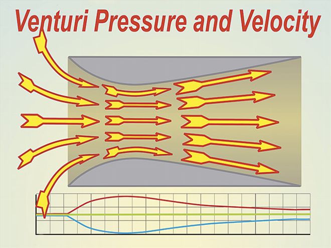 <b>Fig. 1</b><br>Suction by the cylinder pulls air through the venturi. In doing so, it speeds up as it reaches the choke point (as depicted by the red curve on the graph above). As this happens, the pressure drops (blue line). Tapping into the minor diameter of the venturi and connecting it to a fuel supply would result in a simple carburetor.
Having a working understanding of boosters can be an important asset because it will allow the use of a greater carb cfm before any negative impact on low-speed drivability. When Holley started getting into racing in a serious manner (way back when) it became apparent that making bigger, higher-flowing carbs also meant stepping up booster design research. Even to this day, much of that knowledge remains in the possession of but a few individuals working behind tightly closed doors. Compounding this is the increasing dominance of electronic fuel injection, making carburetor booster design somewhat of a lost art. Maybe it's time to spread booster know-how, but before a coherent discussion can be had, at least a brief rundown on how they work and interact with the rest of the carb's functions will be in order.
Venturi Action
The entire function of a booster hinges on what happens when air is drawn through a venturi. Take a look at Fig 1. What you see here is air being drawn through the venturi by the suction (partial vacuum) of the engine. As the air passes through the minor diameter of the venturi, it speeds up, as depicted by the red curve on the graph. When this happens, the pressure of the air drops in the manner shown by the blue line. As the air expands in the exit area of the venturi, it slows, and a pressure recovery takes place. The greater the airflow through the venturi, the greater the pressure drop at the minor venturi. Now we come to the key point of understanding how a booster works: the volume of air flowing through the venturi depends on the amount of suction (pressure drop) there is at its exit end. Now, let us take that same venturi shown in Fig. 1 and insert a smaller venturi with its exit end precisely at the smallest diameter of the larger venturi (Fig. 2). As you can see, the pressure drop (P2) at the smallest point of the main venturi is more than the pressure drop (P1) caused by the cylinder's draw. By having the exit point of a smaller venturi at the point of lowest pressure of the main venturi, the amount of air going through the smaller (booster) venturi will be faster. This is because it is being sucked in not by the smaller pressure drop at P1, but by the much bigger pressure drop at P2. This means the air at P3 is going even faster than that at P2, so the pressure drop at P3 will be even higher. In other words, the booster has amplified, or as we say "boosted," the pressure drop from P2 to P3. So, now you know why it's called a booster. The importance of the pressure drop is that it is the signal that is used by the carb's fuel system to not only meter the amount of fuel for a given amount of air, but also to produce sufficient atomization for the fuel to burn effectively. If either one of these factors are off by too much, power output suffers.
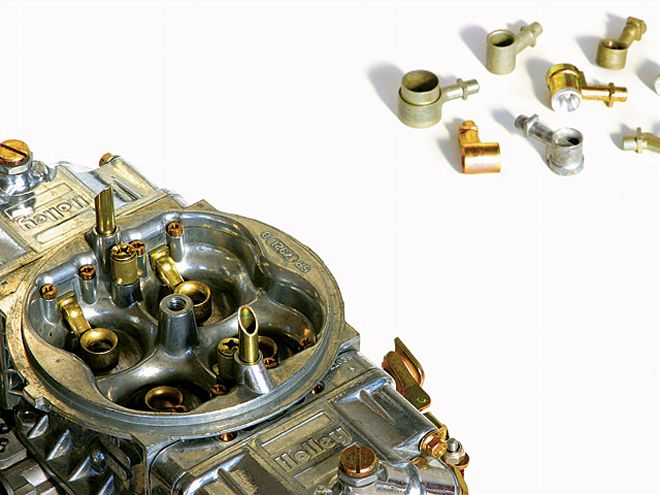
 Selecting the right booster can make all the difference when running a large carb on your street car. From top to bottom: annular discharge, down-leg, and straight-leg boosters. Which one's the best for you? Read on!
Booster Gain
Maximum horsepower calls for a carb with enough airflow to completely satisfy the engine's need at peak rpm. This inevitably calls for a bigger carb than would be required if power at low and mid speed was the main criteria. The bigger the carb becomes, the more critical the booster design becomes if the carb is to operate over any acceptable rpm range. Before Holley could introduce the Dominator series of carbs with its big barrel sizes, the company had to come up with a booster design that produced high gain. In other words, it had to take a relatively small signal as generated at the minor diameter of the main venturi and amplify it into a strong, useable signal for the purposes of metering and atomization. Over the years, Holley has laid down some sterling groundwork in terms of booster design. Fig. 3 shows the characteristic form of the main variants. These are shown in approximate order of gain. For instance, at a typical wide-open throttle pressure drop, the number one booster amplifies the main venturi signal by about 1.8, while a number five booster with all the casting flash removed and a clean-up on the entry and exit delivers an amplified signal nearly four times that of the main venturi. Fig. 4 will give a good prospective of the difference in signal strengths when the five booster styles shown in Fig. 3 are tested in one barrel of an 850-cfm Holley carb.
Boosters and Carb Sizing
If the intent is to have a carb that delivers the goods over a very wide range, then the bigger the carb is for a given engine size the higher the booster gain needs to be. Only by having a very high-gain booster can we expect a large-cfm carb to produce flawless low-speed performance. If we have such a booster it is possible to run 1,000-cfm carbs on engines that would normally have 650 or so cfm considered ideal. The advantage of the bigger carb is that it does allow the engine to make more top end while the high-gain boosters still produce an adequate signal to cater to the metering and atomization of low-speed operation. About now you should be appreciating (in the normally accepted fashion) that there is no such thing as a carb that is too big, only one with an inadequate booster signal.
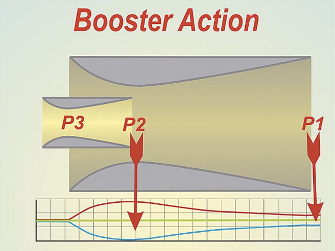 <b>Fig. 2</b><br>Air flowing through the main venturi is dictated by the pressure drop caused by the engine's suction (P1). The air flowing through the booster is dictated by the much greater pressure drop occurring at the minor diameter of the main venturi (P2). This brings about a much higher pressure drop and velocity at P3.
Getting an adequate booster signal by utilizing a high-gain design is not the only way to get your four-barrel carbed engine to perform both at the top and bottom ends of the spectrum. All too often, street rodders make the mistake of assuming if the racers use it they should also do so and that usually means big cfm mechanical secondary carbs. Such a deal just won't make it at the low end, but how about a variable-cfm carb? That would be small at low rpm and big at high rpm. If you like that idea, then the good news is it is readily available and is commonly known as a vacuum secondary carb. If you are into big-blocks, just think what a useful piece a vacuum secondary Dominator would be!To see by how much we could cheat the normally accepted "too big a carb" deal, a basic stock cam/valvetrain 350 small-block Chevy equipped with pocket-ported production line 186 head castings and dyno headers was tested with a Victor Jr. race manifold and an 850 carb. Normally, an engine with such a conservative spec would have been equipped with a 600- to 650-cfm carb. Fig. 5 shows how an 850 with stock or high-gain boosters stacks up against a stock 650. Several lessons can be learned here and the first is not to assume that bigger is better, as the stock 650 showed far better results than the stock 850. When the 850 was equipped with boosters that delivered about the same signal strength per cfm as the 650, a different pattern emerged. With the 850, the low-speed output was almost the same as the 650, but the top end was significantly better.
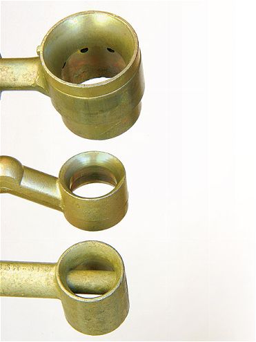
Fig. 3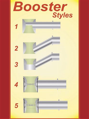 <b>Fig. 3</b><br>Booster number one (straight-leg) is common to many street replacement Holleys. Booster number two (sometimes called a down-leg booster) is often used in performance-orientated carbs. Number three is a dog-leg booster with a step machined into the underside. This is a popular hop up move used by carb specialists to assist fuel atomization. Number 4 is a stepped annular discharge design while number 5 is a similar annular discharge style but without the step. The last two styles are the high-gain types most often used in big-cfm carbs.
Atomization Requirements
Looking at the results so far, it would seem that the more gain a booster has, the better our carb will work. That assumption is indeed correct if we are looking at a wide operating band, but if it's a race engine where optimizing output over, say, 2000 rpm, is the goal then things are a little different. Why? Because it is possible to have a booster that brings about a too finely atomized charge. The smaller the fuel droplets are, the more readily they evaporate into a vapor. When a droplet becomes vaporized to a gas, it takes up much more room in the intake and cuts the volumetric efficiency of the induction system. Although a charge of vaporized fuel and air will display about the best combustion characteristics, it won't produce the best power because the amount of air in the cylinder with the vaporized fuel is less than with liquid fuel. Although a charge with fully vaporized fuel delivers the best in terms of drivability and fuel efficiency, to make maximum power a certain optimum droplet size is required.
At this point it may look like an easy task to develop a booster that delivers the required droplet size, and the job is done. Unfortunately, life in general, and high-performance engines in particular, are rarely that simple. In practice, there are many factors that influence what happens to the fuel after it leaves the booster. The most important of these is how well the fuel stays in suspension in the air and the temperature of the induction system. Ports with a high, uniform velocity and good wet-flow characteristics are a good start, but unless you are in the cylinder head business you probably don't have much influence over that factor other than to choose your cylinder heads wisely.
Fig. 4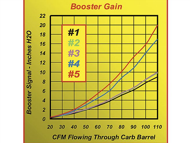 <b>Fig. 4</b><br>This graph shows the signal strength for each of the booster styles depicted in Fig. 3. Note the big difference between the lowest and highest.
Where you can have a significant influence as an engine builder is on the induction temperature. What arrives at the cylinder is an air/fuel mix with a range of droplet sizes from very small to some very large ones (and a fair amount of fuel arriving in rivulets). These larger droplets will not ignite very easily and do not become part of the combustion process until the fuel that is ignitable has created enough heat to vaporize them. This means that a certain proportion of the air/fuel mix entering the cylinder needs to be in an easily ignitable vapor form. Without some vapor the ignition and subsequent burn will not be anything near effective. In simple terms, this means that the cooler the intake charge becomes, the more finely atomized the fuel delivery needs to be as finer droplets evaporate easier. Where power is the sole concern, the basic rule here is to use low-gain boosters for heated intake manifolds and high-gain boosters for cool manifolds. If you are experimenting with thermal barrier induction systems and/or artificially cooled intakes then be aware that without re-evaluating the booster design, you may not see the gains in output you hoped for.
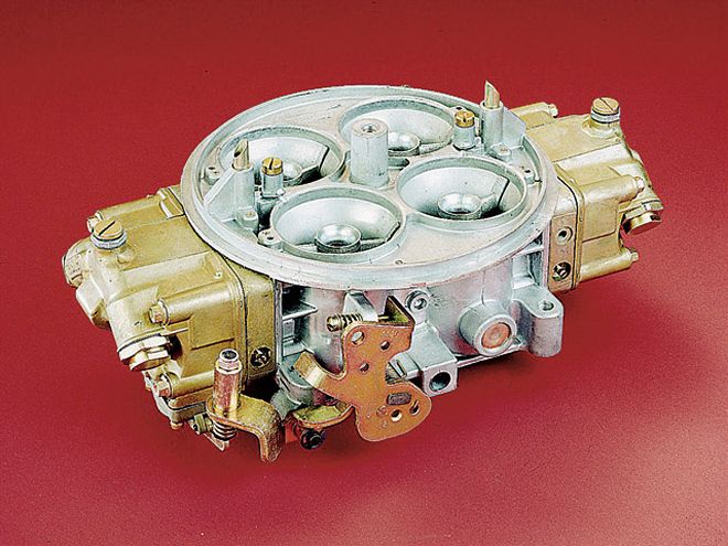 Big-cfm carbs, such as this Dominator, are able to produce top-notch results over a wide rpm range mainly because of high-gain annular discharge boosters.
What's It Worth?
Some tests we ran a few years ago with a well-known Cup Car carb builder illustrates just how much your engine could gain or be loosing by failing to get the right booster for the job. For this test, two carbs, one with high-gain boosters and one with low-gain boosters, were used. Each was run on an engine that was first equipped with an aftermarket manifold that had crossover heat applied. The second, a Victor Jr, had no crossover heat and was air-cooled. In Fig. 6 we see a comparison between low-gain boosters delivering relatively large droplets and high-gain boosters delivering considerably finer fuel atomization. With the larger droplets, a nearer optimal percentage of the fuel is vaporized by using the low-gain boosters. The result is that they outperform the high-gain boosters, which, because of the smaller droplets delivered, have too much vaporization going on. Fig. 7 shows the same two booster styles tested, but this time the engine has a Victor Jr., which not only lacks added intake heat but also has an air passage under the runners to allow further cooling of the intake. Bear in mind that this is the same engine as Fig 6. What we see here is that the carb/booster combo that worked best on the heated intake manifold did not work very well on the Victor Jr. Note how this carb dropped a huge amount of low-end torque. In many instances this would have been accepted as a shortcoming of the Victor Jr. intake. After all, what we are looking at is a back-to-back test (Fig. 6 low-gain booster versus Fig. 7 low-gain booster). In reality, the Victor Jr. has much more low-speed potential than it is often credited with. It's just a case of having adequate fuel atomization. The golden rule here is: "drop intake temperature, boost atomization." If you fail to do that, your cool intake system may not show its full potential. Indeed, drop that intake temperature enough with an indifferent booster design, and you may find your efforts are rewarded with less power rather than the increase you expected!
Manifold Design
A single-plane open-plenum manifold may be the manifold to go with if top-end power is the goal, but dual planes (180-degree-style) are often short-changed when top-end output is considered. In an effort to do things right, the conscientious hot rodder may well size the carb using commonly published and accepted sizing formulas. The problem here is that a two-plane manifold divides the carb capacity in two and this is often not allowed for when computing the required carb cfm by conventional means. Modern high-flow, cool-running two-plane manifolds dictate the use of a booster that will produce the appropriate atomization. In addition to this, they need enough total carb cfm to compensate for the fact that each cylinder sees only two barrels of the carb, not four as per an open-plenum design. Getting the booster design right and having enough total cfm will endow a modern two-plane manifold with way more top-end than they are often credited with. On top of this the more appropriate atomization can also add a measurable amount of low-end into the bargain. We have successfully used as much as 1,050 cfm of carb capacity on a 383 small-block equipped with a two-plane manifold. This makes the idea of a 1,200-cfm Dominator on a good, two-plane intake very appealing for a big-block application. We wonder if any manifold manufactures will step up to that!
Booster Hop Up
Except for maybe converting a regular booster to a stepped booster, there is not much you can do to alter the basic design of a booster. That does not mean the signal gain can't be improved. Take a close look at a booster and you will see that it has a flat-face top and bottom about 25 thousandths wide. It's there because the casting process typically used to make boosters cannot produce a sharp edge. Removing a little metal from the booster's inner form as per the diagram will produce an increase in signal far beyond what you may expect from such a minor mod. It does so because the sharp edge causes more air to go through the booster rather than be deflected around the outer diameter. This mod also produces a couple of extra cfm per barrel so it is definitely a win-win move.
Another popular move is to convert the so-often-used dogleg booster to a stepped-style design. The step does little to increase the booster signal, but it does bring about better fuel shearing at the discharge point, thus causing the fuel to atomize better.