
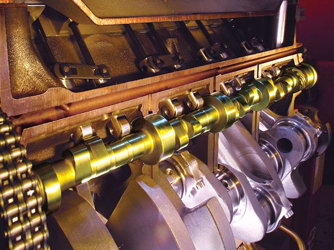
Performance may always lay heavy odds on power, but you also need the brains to go with it. The four-stroke internal combustion engine has been around for over a century, but we're still learning incredible things about using camshafts to make more power. That elliptical lobe may look simple, but it represents the brains for your engine's brawn. Let's take a look at what makes this simple eccentric device so powerful.
Lift
We'll start with the easiest concept involved with the camshaft--lift. A cam lobe starts off from a simple circle, called the base circle of the cam. From that circle, the designer creates additional lift using a ramp so that as the circle rotates, it converts rotation into a linear or vertical motion by using a follower or tappet. This lift eventually rises to its highest point beyond the basic radius of the circle. The difference in height between the top of the lobe and the radius of the circle is the lift component of a cam lobe. For most street-type cams, this will be roughly between 0.275 and 0.450 inch. This is called the lobe lift of the camshaft. But we don't generate this lift all at once--it's created by gradually moving the tappet from the base circle to maximum lobe lift. This is where duration comes in.
 Lobe design can vary immensely, even within a family of camshafts. The key to selecting the right cam is to match it not only to the type of use the engine will see but also to the other components in the engine. The goal is to create a strong overall power curve.
Duration
Ideally, you could slam a valve open, hold it open, and then slam it closed, and many drag race camshafts attempt to perform this feat, but this harsh action is incredibly abusive on valvetrain parts, especially valves and springs. To make these parts live over hundreds of thousands of miles, the cam lobe lift curve must be gentler. The easiest way to measure the amount of time the lobe is creating lift is with degrees of duration. A long time ago, our cam-building forefathers decided to use crankshaft degrees to measure cam lobe duration. So a typical performance camshaft may have a duration of 280 crankshaft degrees. Keep in mind that a camshaft actually spins at half engine speed.
But this created confusion because all the different cam companies measured the beginning of the lift curve at different points a few thousandths of an inch above the cam's base circle. This is called advertised duration and it can get complicated because, for example, Comp Cams begins measuring its advertised duration for hydraulic lifter cams when the lifter rises 0.006 inch off the base circle. Crane uses 0.004 inch, which would make the same lobe "appear" a few degrees longer in duration because the duration would be measured over a 0.004-inch-longer distance (0.002 inch on the opening and closing sides added together). This difference between companies eventually led to the selection of 0.050 inch as the standard checking point where all the different companies' lobes can be compared. So now we have both advertised duration and duration at the 0.050-inch checking figure. Now that you have the basics, we can dive into a few more items that make camshafts complex, but also fun.
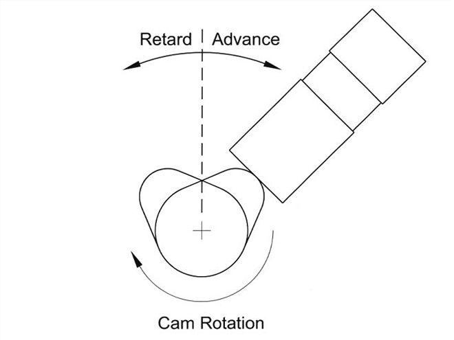
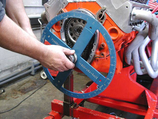 The best way to install a cam is to degree it into the engine so you know exactly "where" the cam is located. Advancing the cam will move all the lobes to open and close sooner in the cycle. Generally, advancing a camshaft will increase low- and mid-range torque at the expense of some top-end power.
For each lobe there is an opening and closing point. Let's say you are measuring an intake lobe on a camshaft in the engine using a dial indicator and a degree wheel. Once the lifter rises off the base circle 0.006 inch, let's say that the degree wheel reads 20 degrees before top dead center (BTDC) and closes 90 degrees after bottom dead center (ABDC), then you can add those two numbers together along with 180 degrees and come up with the advertised duration: 20 + 180 + 90 = 290 degrees. This same formula can also be used to determine duration at 0.050 inch tappet lift.
Duration is a major contributor to the torque curve and where it occurs in the engine's rpm band. Generally speaking, as you increase the amount of intake lobe duration, this makes for an earlier-opening and later-closing intake valve. This additional duration also extends the rpm point where peak torque occurs. This tends to increase peak hp (depending upon the other components used on the engine) while sacrificing low- and mid-range torque. Conversely, a very short duration camshaft opens the intake valve later and closes it sooner, reducing the potential for high-rpm horsepower but increasing torque at a lower engine speed.
Intake Centerline
Now that you have lift and duration mastered, we can move on to more of the measurement values in camshaft design. Imagine looking at a lobe with a vertical line running right down the middle as viewed from the end. This line would represent the centerline of the lobe. If this were an intake valve, this would be the intake centerline of the lobe. Cam designers and engine builders use this centerline to establish where the lobe is located relative to the piston. For example, a Comp Cams 268 Xtreme Energy cam has an intake centerline of 106 degrees ATDC. This means that the midpoint of the lobe (which may or may not be maximum lift, since some cams are asymmetrical in design), will occur when the Number One piston is positioned at 106 degrees after top dead center.
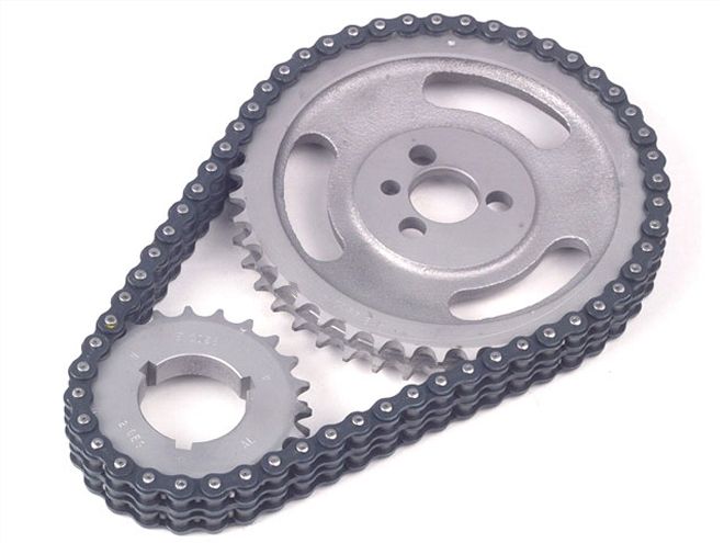 The camshaft spins at exactly half crankshaft speed, which is easy to tell with the timing chain and gear, with the cam gear twice the size of the crank gear. Performance gear and chain sets often allow you to easily advance or retard the cam with optional slots on the crank gear.
When installing a camshaft in an engine, performance engine builders and the blueprinting process demand that you measure or "degree" the camshaft to ensure that it is installed where the engine builder desires. It's not enough to merely line up the dots on the cam and the crank gear. This way, if the engine builder would like to change the phasing of the camshaft, he can use that installed point as a reference. It's tough to know where to go if you don't know where you are.
This phasing of the camshaft is important because when the valves open and close has a serious effect on engine performance. This is where we get into advancing or retarding the position of the camshaft relative to the Number One piston. All references to positioning a cam are always around the intake lobe for the Number One cylinder. So if we wanted to advance the previously mentioned 268XE cam with its 106-degree intake centerline by 2 degrees, this would open the valve earlier in the cycle. It would place the intake centerline at 104 degrees after top dead center (ATDC).
Conversely, if we wanted to retard the camshaft by 2 degrees, this would move the original 106-degree centerline to 108 degrees ATDC. This is an important point that many people get backwards, so take a minute or so to study why these numbers are correct by looking at the cam timing graph.
Advancing the camshaft means that you are starting the opening and closing process sooner in the cycle. It generally improves low-speed torque and mid-range power while sacrificing top-end hp. Conversely, retarding the cam detracts from low- and mid-range power in order to help top-end power. Generally, moving a camshaft a couple of degrees will not make dramatic changes to the engine's power curve.
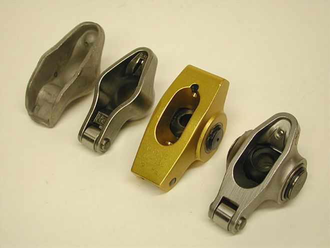 The camshaft is only one part of the overall valvetrain. Rocker arms are also important players in the overall engine performance scheme. From the left is a stock stamped steel rocker followed by a roller-tipped rocker, and then a series of different design true roller rocker arms.
Lobe Separation Angle
Here's where we get into some meaty stuff, so stay with us. If you look at the lobe graph, you can see the relationship of the intake and exhaust lobes. One of the variables that make cam designing such a challenge is the relationship of the intake to the exhaust lobe. The number of degrees between the intake and exhaust lobe centerlines establishes what is called the lobe separation angle. As an example, many Crane street camshafts are built using a 112-degree lobe separation angle. This means there are 112 camshaft degrees between the exhaust and intake centerlines. This can be determined from a cam card by adding the exhaust and intake centerline numbers together and then dividing by 2. So if you add a 111-degree exhaust and a 113-degree intake lobe centers and divide by 2, you'd get a 112-degree lobe separation angle. Keep in mind that often the intake centerline and the lobe separation angle will be the same number, but they represent completely different functions.
Valve overlap is a function of both duration and lobe separation angle. If the lobe separation angle remains the same but you increase the duration, the amount of overlap will also increase. Overlap is the time, measured in crankshaft degrees, when the exhaust valve and intake valves are both open. Overlap helps improve engine performance by starting the intake cycle before the exhaust cycle has ended. As overlap increases, this tends to make the idle quality more erratic, or lumpy, while improving midrange and top-end power. This is a very complex subject that we'll just touch on here, but even slight changes in overlap and intake opening and closing points can make a big difference in engine performance.
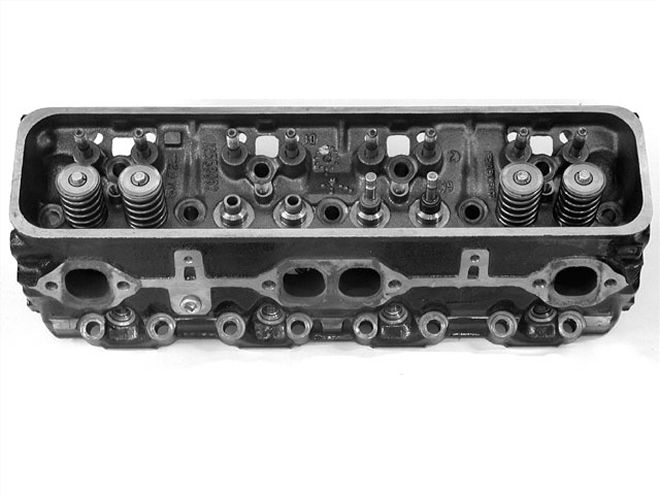 Valvesprings are also a critical component that should not be overlooked when building a performance engine...
Single- and Dual-Pattern Cams
As we learn more about camshafts, you find that the early cams tended to be relatively simple devices that have become increasingly complex, yet far better in terms of increasing engine performance. In the early days, intake and exhaust lobes were almost always the same. These were called single-pattern cams. But it didn't take the race-engine builders long to realize that often the engine's exhaust port was not as efficient as the intake and needed more duration to help scavenge all the exhaust gas out of the cylinder, especially at higher engine speeds. This demanded a longer-duration lobe on the exhaust side of the camshaft. These cams became known as dual-pattern cams.
Dual-pattern cams are now commonplace in even mild street engine camshafts. Ironically, as performance cylinder heads continue to improve, their exhaust ports are also achieving parity with the intake side of the heads, so the single pattern cam is again becoming popular, especially when combined with the better aftermarket small- and big-block cylinder heads.
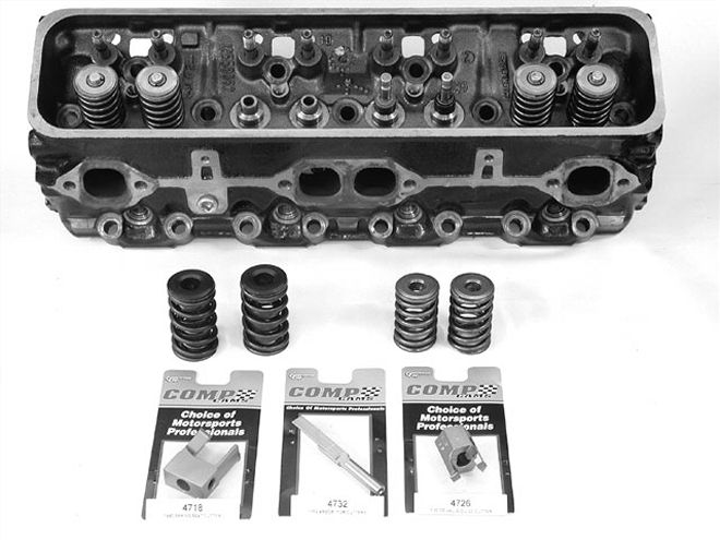 ...Weak valvesprings can allow the valves to bounce off their seats, robbing power with virtually no warning.
Cam Selection
Now that you have a general understanding of these concepts, you can employ them to help you in selecting your next camshaft. Of course, there are libraries full of additional material when it comes to camshafts, and we haven't even touched ideas such as adding higher-ratio rocker arms and how important valvesprings are to making power. Perhaps the most important point to make when getting into the cam selection process is that you need to focus on how the engine will be used. Camshafts have a major impact on where the torque curve begins and ends, and it seems like everyone always wants to use the biggest cam they can physically squeeze into the engine. This "bigger hammer" approach rarely is successful and usually results in a sluggish engine that doesn't make power anywhere. Taking a conservative approach to cam selection may not always make the most power, but it will offer an engine that can make respectable power over a broader rpm band, which is always useful for street engines expected to run well between idle and 6,500 rpm or more. In other words, that killer lumpy cam may sound nasty, but it rarely works well in a daily driven street machine.
 This illustration reveals how an eccentric is added to a simple circle to create a cam lobe. Note how the height of the lobe above the circumference of the circle represents total lift.
Conclusion
Armed with these basics of camshaft operation, you should be able to see why selecting a camshaft is not as easy as you might have thought, and that this simple-appearing device is actually incredibly complex set of mathematical models that have a headlock hold on the engine's power curve. The good news is that most street performance camshafts are relatively affordable and easy to exchange in the engine. So if you make a mistake, it is easy to rectify. But regardless of whether you're a racer or cruiser, a hard-core engine master or a first-time car crafter, there's a ton of information to learn so that you can be the cam guru on your block that everyone turns to for the correct information.
Types of Cams
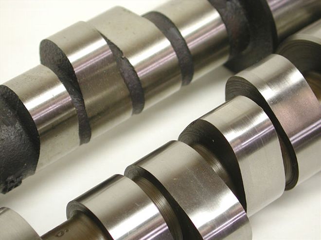
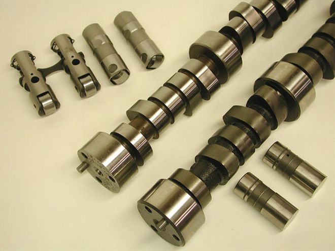 Flat tappet cams (foreground) tend to be less expensive than roller cams, but the rollers offer some distinct advantages.
The basics apply to all camshaft designs, but it's worthwhile to also go over the different lifter applications. The most basic type of lifter is the mechanical flat tappet. While these tappets look flat, they are actually ground with a slight crown in the center that allows them to rotate in the lifter bore. These lifters are designed to operate with a clearance, or lash, usually set between the rocker arm and the valve stem tip. The next is the hydraulic version of the flat tappet. The hydraulic tappet uses a small piston inside the tappet that allows for expansion and clearance changes with a small amount of preload. This preload eliminates the need for semi-regular maintenance to check lash on mechanical flat tappets.
While roller cams may appear to be a relatively recent performance engine phenomenon, the reality is that roller cams go back almost to the earliest performance engines. The roller eliminates a major source of friction in the engine but does require a much stronger steel core as opposed to cast iron for the flat tappet cams. These steel cores, along with the increased cost and complexity of a roller tappet, are the major reasons that roller cams cost more. But as you'll see if you read our "Cam Secrets" story on page 40, there are significant power gains to be made with roller cams.
Lobotomy 101
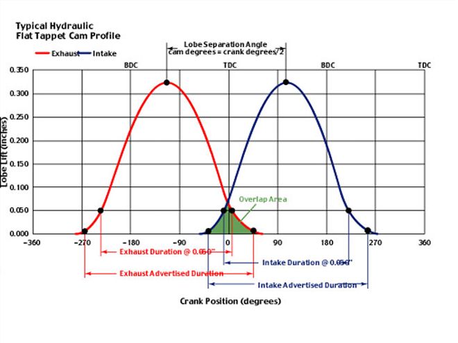
If you take some time to study this graph, it will probably make the concept of cam timing a little easier to understand. Starting on the far left side, the vertical scale is the amount of lobe lift in inches while the horizontal scale is crankshaft degrees through 720 degrees or two full revolutions of the crankshaft. This is because the cam spins at half engine speed.
The first lobe (in red) is the exhaust lobe. You can see how advertised duration is greater than duration at 0.050. At the top of each lobe is a point indicating the lobe centerline and how the lobe separation angle in degrees can be computed by adding the centerline points and dividing by 2, since this angle is expressed in camshaft degrees.
The most interesting point in this graph is the small triangle created by the overlap of the exhaust closing and intake lobe opening points. This area will change depending upon the amount of duration in either lobe as well as the position of either lobe centerline. Any change to any of these dimensions will have a major impact on valve overlap. For example, if you merely increase duration in the intake lobe but leave everything else the same, overlap will increase. If you tighten the lobe separation angle from, let's say, 112 degrees to 108 degrees with no other changes, that will increase overlap, making that little triangle area larger. Keep in mind that in order to change lobe separation angle, you will have to have a new camshaft ground.
There are literally dozens if not hundreds of variables that you can plug into this basic graph to help you see the effect of even the slightest camshaft changes. This can help you visualize the changes that a cam makes to the engine.