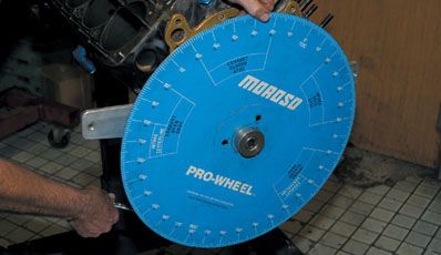
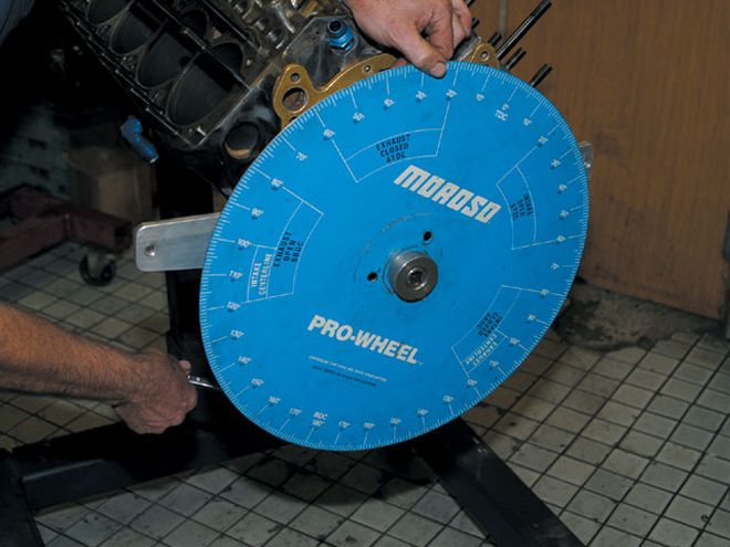
 Pletcher bolted the degree wheel onto the crankshaft. The wheel has a notch for the keyway on the crankshaft making it impossible to install incorrectly.
When you buy a camshaft out of the box these days, you can be reasonably certain it will be close to where you need to be in terms of the grind. Much of that is because of advances in technology available to the cam manufacturers. However, as any good racer knows, you can never take anything as important as your camshaft at face value.
So, it's always a good idea to synchronize your camshaft to the crank before you count on it to deliver race-winning horsepower. There is no magic to degreeing your cam: simply bolt a degree wheel to your crankshaft and check it the way engine builders have done for many years. The purpose of degreeing a camshaft is to synchronize its rotating position with the crankshaft. This is the only way to know that the valves are opening and closing in accordance to the rise and fall of the pistons as intended for peak performance. To phase in the camshaft, the manufacturer's data (the cam card) has all the information you need on where that particular camshaft needs to be degreed.
To get a better step-by-step understanding of this process, Circle Track magazine went to Dave Pletcher of Pletcher Racing, Inc. to get useful cam degreeing info. Pletcher builds engines and drives his own Sprint car in the fast and furious world of the Tampa Bay Auto Racing Association.
The most common method of degreeing a camshaft is the centerline method, this will not work with most modern-day performance camshafts. While conventional lobes have the same shapes on both sides of the lobe, a modern-day camshaft's lobes are asymmetrical or not equal on both sides. Therefore, the industry-standard method to get an asymmetrical camshaft degreed correctly is to use the 0.050-inch of lobe lift method. This measures the camshaft at 0.050-inch of lift regardless of the shape of the lobes. "The 0.050-inch method is the only way a cam gets degreed in my shop," said Pletcher.
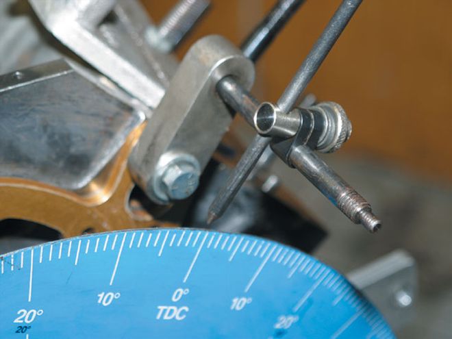 The pointer needs to be attached to a secure spot on the block where it will not move. If the pointer moves the readings will not be accurate and you will have to start from the beginning.
Finding True Top Dead Center (TDC) The first step in degreeing a camshaft is finding top dead center on the No. 1 cylinder. Once the crankshaft, cam, and pistons are assembled in the block, the timing gears are bolted on with their index dots/indents aligned. Now, rotate the engine so that the No. 1 piston is approximately at TDC. Next, the degree wheel is bolted to the crankshaft using a keyway for alignment. "Use the largest degree wheel you can find," Pletcher said. "The larger wheel has more room for the tic marks, making it more accurate, especially when it comes down to small differences."
A steel timing pointer (coat-hanger wire, for example) is mounted to the block and pointed at the degree wheel. Make sure the degree wheel's zero mark is aligned with the pointer. You may have to bend the pointer or rotate the wheel to achieve this indexing without turning the crank. With the degree wheel and pointer locked in position, you're ready to attach a piston stop to the block. "The most common problem I see is that people don't use a positive stop and only estimate top dead center (TDC)," Pletcher said. "Then the camshaft is off a long way. Finding the true TDC of the No. 1 cylinder is the most important step when degreeing a camshaft. The piston can dwell at TDC for 6 to 8 degrees of crankshaft rotation, making for a large margin for error."
Pletcher mounted a positive stop on the block over the No. 1 cylinder. There are a couple of ways to attach the positive stop. One type screws into the spark-plug hole and the other is strapped across the top of the cylinder (if the head has been removed). On the second type, which is the most accurate, a bolt extends from the stop into the cylinder bore. The bolt makes contact with the piston, stopping rotation. The bolt on the screw-in spark-plug hole stop sometimes cannot contact the piston in some of today's high-performance heads, particularly the aluminum heads, because of the spark-plug angles in such heads.
 Before any calculation can be done, you need to find true TDC on the No. 1 cylinder. Pletcher mounted a positive stop tool onto the cylinder so he could find TDC.
Pletcher then hand-rotated the engine clockwise until the piston made contact with the positive stop and recorded the degrees indicated on the degree wheel. In this case, it was 38 degrees before top dead center (BTDC). Next, the engine was rotated by hand in the opposite direction, counter-clockwise, until it once again made contact with the positive stop. This time, the measurement was 32 degrees after top dead center (ATDC). Add these two numbers (38 degrees BTDC and 32 degrees ATDC) together and divide by 2 (38 + 32 = 70/2 = 35). Without turning the crankshaft, move the pointer to the 35-degree ATDC mark on the degree wheel. To check that the pointer was properly set, Pletcher hand rotated the crankshaft in both directions, touching the positive stop to make sure the pointer hit the same spot on the degree wheel. Now the degree wheel and crank, when set at the zero-degree setting, marks the true top dead center of the No. 1 piston.
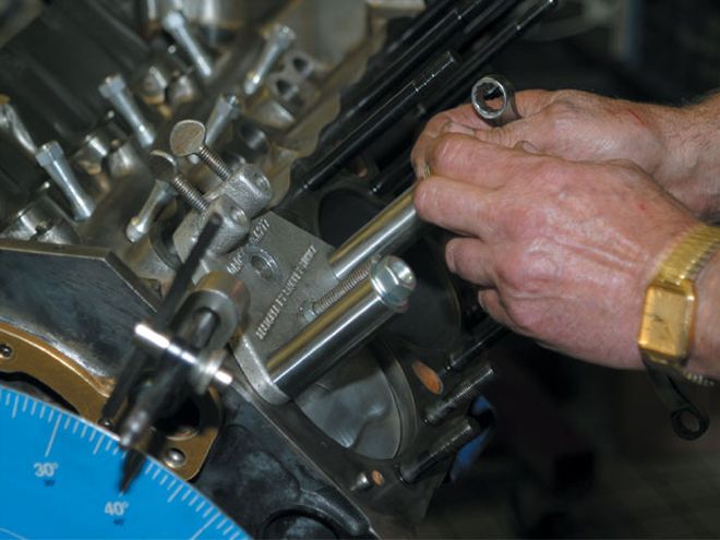
At 0.050 Of An Inch Next, Pletcher inserted a lifter bore dial indicator into the No. 1 cylinder intake lifter bore to measure the lift on the lobe. Make sure you are measuring the intake lobe-if you are measuring an exhaust lobe, the numbers you get will be crazy. When doing this, make sure there isn't any grease-like break-in lube on the lobes, which can skew your readings on the degree wheel.
Pletcher then hand-rotated the engine clockwise, the normal operating direction (opening side of the lobe) until the dial indicator read 0.050 inches of lift, the industry standard checking height. Pletcher recorded the reading indicated from the pointer on the degree wheel, matched it to the cam card and then hand-turned the crank clockwise again to verify the maximum lift on the cam card. As the dial indicator started to decrease, Pletcher stopped rotating the engine at 0.050 inches on the closing side of the lobe. Once again, a reading was taken and recorded from the degree wheel and matched to the cam card. Pletcher continued to rotate the engine to make sure the dial indicator returned to zero at the base circle side of the lobe. Using these two readings, you can verify that the cam is matched to the cam card's specs. "I always repeat this a minimum of twice," Pletcher said. "There's always a chance that the dial indicator slipped or the degree wheel came loose on the crankshaft. Checking your work to make sure you get the same readings will prevent problems later on."
Confirming Duration We wanted to check some of our measurements to see how they matched our cam card. To calculate duration on the No. 1 intake lobe, we took our readings at 0.050-inch and found they were 27 degrees BTDC (opening) and 59 degrees after bottom dead center (ABDC, closing). To calculate duration, add these opening and closing values (27 + 59 = 86), and then add 180 (180 is the number of degrees between TDC and BDC). This (86 + 180 = 266) equals 266 degrees duration. To find the intake lobe centerline, divide the duration (266) by 2, and then subtract the opening value (27 degrees): 266 / 2 = 133 - 27 = 106 degrees intake lobe centerline. Apply the same formula to get the exhaust lobe values, if you choose to check them.
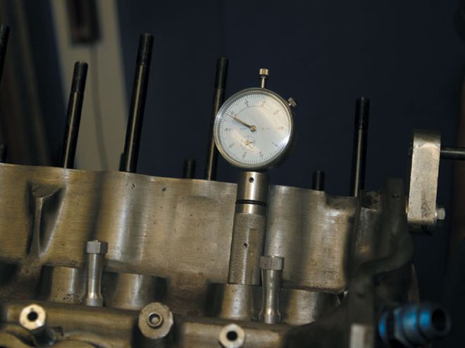 A lifter bore dial indicator is used on the intake lobe of the No. 1 cylinder to check when the lifter is at 0.050-inch of lift on the opening side of the lobe and the same on the closing side. At these points, the degrees are checked with the manufacturer's specification on the cam card.
Tools NeededM
In order to perform the task of degreeing a camshaft, you will need the following tools:
* A degree wheel. It is best to pick the largest degree wheel you can find. The larger the wheel the more accurate it is.
* A pointer to point at the degree wheel. The pointer should have a stable base that can be attached to the engine block where it will not move.
* A dial indicator with a stable base. This needs to read in 0.001-inch increments at a 11/42-inch of travel.
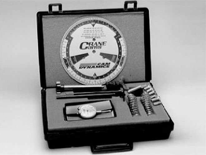 Crane Cams offers a Tune-A-Cam kit (PN 99030-1) that contains all the necessary tools needed to degree a cam. This kit can also be used to check valve-to-piston clearance.
* A positive stop device to locate TDC. You can make one of these by using a piece of angle iron that is bolted to the block at the head bolts with a bolt protruding into the cylinder. An old spark plug with the porcelain drilled out and tapped for a bolt that will act as the positive stop can also be used when the heads are in place.
Camshaft Terms
Asymmetrical Lobe: A camshaft's lobe that has a different profile on both the opening side and the closing side.
Base Circle: Is the backside (heel) of the camshaft lobe.
Centerline: The point of a lobe that has the maximum amount of lift. This is commonly used as a reference point when degreeing a camshaft.
Degree Wheel: A flat metal disk with measurement in degrees. The measurements start at 0 degrees going a full 360 degrees in increments of 1 degree or less than 1 degree. A degree wheel is bolted onto the crankshaft while in use.
Dial Indicator: A measuring instrument used to measure rotating parts, such as cam lobes.
Duration: How long a valve is open during crankshaft rotation. This is usually measured at 0.050-inch of valve lift on the opening side of the lobe to 0.050 on the closing side of the lobe because there is little airflow at low lift values. It is stated in degrees of crankshaft rotation.
Lift: The distance a valve rises off the valve seat. This can vary depending on the rocker arm ratio, valve lash and pushrod deflection.
Lobe Separation (angle): This is the degrees measured between the maximum lift on the intake lobe and the maximum lift on the exhaust lobe. This cannot be changed without regrinding the camshaft.
Positive Stop Device: A tool that is used to prevent motion beyond a given point.
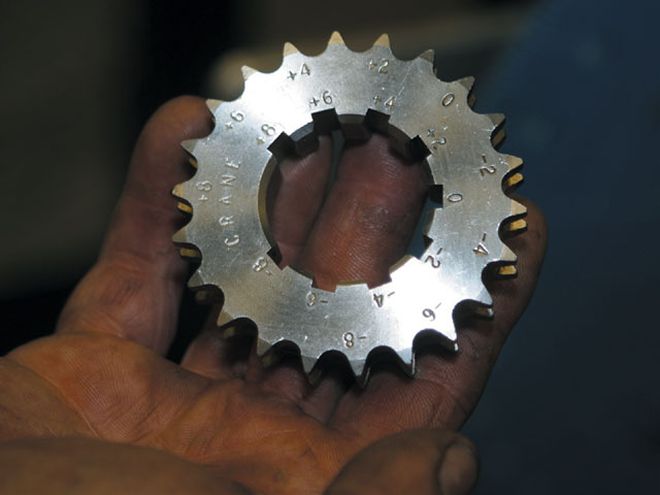
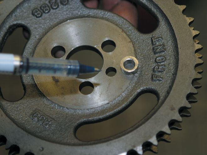
Adjustment, Advancing, Or RetardingIf the camshaft isn't corresponding to the cam card, there are several methods of adjustment that will move the camshaft into the correct position. The smaller sprocket on many timing-chain sets has three or more keyways. By using any of the different keyways you can advance or retard the camshaft. When using this method, there are matching numbers on the larger sprocket that need to be matched to what you set the smaller sprocket on. Also, you can use eccentric bushings in the upper sprocket. These bushings are put in the aligning dowel pinholes and can be turned to advance or retard the camshaft timing. When using this method, the mounting holes will need to be drilled out so there is room for the gear to be rotated. Another option is the use of an offset key on the crankshaft. This method, just like the multiple keyways in the smaller sprocket, works by turning the gear to either advance or retard the camshaft timing.
Do not confuse advancing or retarding the camshaft with degreeing it. Degreeing the cam consists of checking the installed centerline location of the camshaft and the opening and closing point of the lifters at 0.050 inches on the lobe. Advancing or retarding the cam by use of cam gear bushings or the crank gear changes only the installed position of the cam relative to the crankshaft. When you change the cam's phasing, it causes all lobes to open or close sooner or later relative to the position of the crankshaft.
You might want to advance or retard your camshaft to increase performance. By advancing or retarding the cam, you can change the torque curve to better match track conditions. For example, and depending on the cam's grind, a 2-degree advance of the camshaft can move the powerband approximately 100 rpm sooner, while the same degrees of retard can cause the powerband to come on 100 rpm later.