Technology is one of those things that can be either a huge burden or a huge convenience, depending on how you look at it. Anyone who’s driven a car less than 10 years old is probably familiar with things like automatic door locks, electric windows, perhaps even remote start capabilities. But for most of us, those types of modern amenities aren’t present when it comes to our old trucks. Thankfully, if you’re a bit of a technophile like myself, the latest and greatest technological, whiz-bang gizmos found in the current crop of contemporary automobilia eventually trickle into the automotive aftermarket.
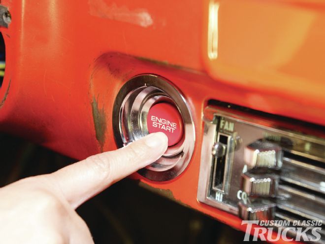
One of the more recent developments that were only available in the most exotic marquees only a few years ago is the keyless ignition. Available in a variety of forms, from the most advanced RFID-detected, keyless setups to the basic FOB-activated system, this technology has made its way into the aftermarket and not only helps lend a more contemporary feel to our classic trucks, but it adds a whole new level of security than the simple keyed ignition could ever hope for.
Flaming River has expanded upon their popular line of steering components to include a brand-new keyless entry system that uses a FOB-based docking station and push-button ignition combined with a keyless entry module that allows the user to enter their vehicle with the push of one button and fire it up with a second, all while utilizing the latest in random code-generated security.
The system is controlled by the near reader module, which is basically the brain of the setup. It’s wired directly to the docking station that communicates with a computer chip built into the key fob. Once the key fob is in place, the docking station gives the “OK” to the module and the push button becomes active, allowing the user to enter accessory, ignition, and start modes via the push of the button. A set of three relays then send the signal from the switch out to the corresponding set of inputs.
I really like integrating contemporary technology into the old trucks, especially if it can be done without harming the vintage aesthetic. With my ’68 C10, I’m tweaking a few things to give it a slightly modern vibe, but I don’t want to go overboard. With the addition of the keyless kit, I opted to get rid of the stock ignition switch, replaced by a push button from a Honda S2000. While the idea of using something borrowed from an import caused a bit of a dilemma at first, I quickly got over it once the button was mocked up in place. It fit the overall feel I wanted for the truck and wasn’t overly out of place. The docking station on the other hand was a bit harder to sort, but I figured out a pretty slick location for it and in the end, it turned out better than I had expected. Check out the install and you’ll see what I mean, then head over to www.flamingriver.com and check out their keyless ignition line for yourself.
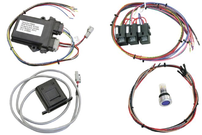 1-4. Flaming River offers a few different push-button start kits with a variety of different functions. We’re using the keyless ignition kit that incorporates an in-dash docking station and keyless entry. The kit consists of a near reader module, a relay harness, docking station, push-button switch, and remote keyless entry system. The near reader module is the brain behind the system, communicating between the push-button switch and the respective functions (start, accessory, etc.) via the relay harness, which protects the switch and module so that they don’t bear the brunt of the electrical load.
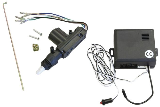 5-6. Complementing the keyless ignition feature is the remote keyless entry (RKE) system. This consists of the ECU and four actuators; one master and three slaves. The master actuator is typically installed in the driver side door and is used to trigger the other actuators; unlocking the driver’s door triggers the other actuators to do the same.
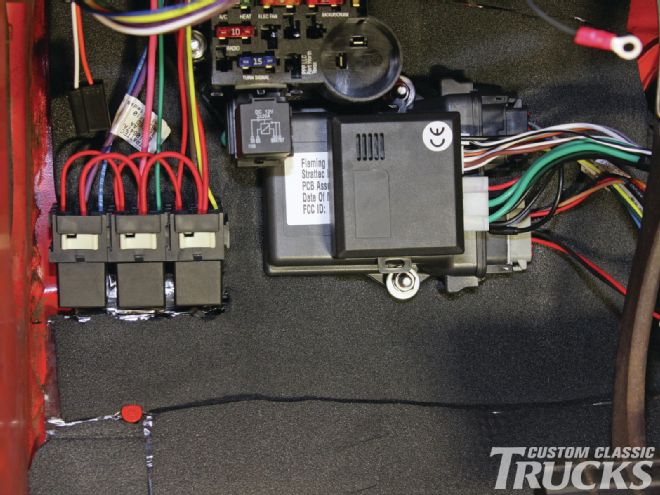 7.The first step is to mount the near reader module, relay harness, and RKE ECU. I opted to place them all in close proximity to the fuse panel to keep the wiring short and easy.
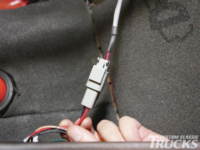
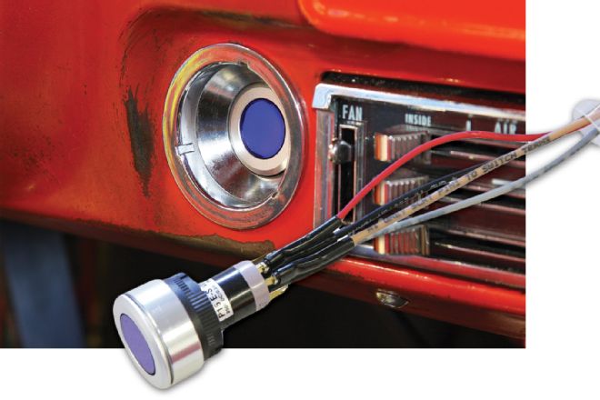 8-9. The next step is wiring up the push button using the provided switch harness. The tan and gray wires on the harness connect to the corresponding wires on the main wire harness that attaches to the near reader module, while the red wire needs to be run to a 3-amp fused unswitched, dedicated hot 12A+ source, and the black wire to a common chassis ground. The button is designed to mount in a 7/8-inch hole, but can be mounted in any interior location.
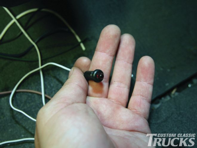
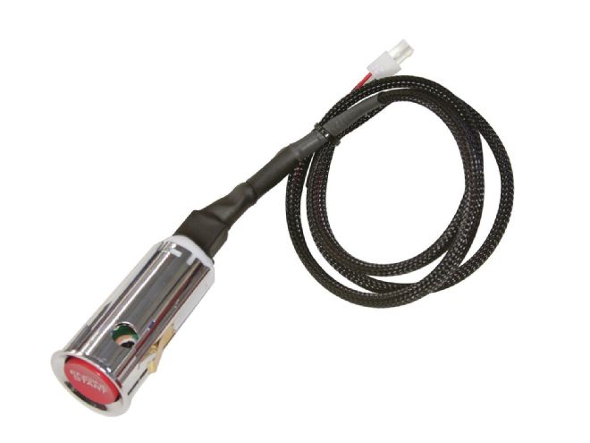 10. For our install, I opted to use a button from a Honda S2000 that will be wired in lieu of Flaming River’s button.
 11-13. While wiring the switch itself is fairly simple, it’s not quite so straightforward when it comes to mounting it in the stock ’68 C10 ignition switch location. The bezels themselves need to be opened up and some way to affix the button needs to be sorted out. In the stock application, the button snaps in place on the dash, but the thickness of the C10 bezel prohibits that from being possible. I whittled out a small retainer ring that fits around the button’s housing and can be held in place using a hose clamp. Slide the button and the outer bezel into the stock ignition hole in the dash, slide the spacer, retaining ring, and hose clamp onto the switch from behind the dash, and tighten the clamp until everything’s nice and snug.
 14-15. Next, we’re going to mount the docking station in the dash. Since the ashtray is no longer used and it’s in close proximity to the driver, I opted to modify that space to locate it. A template is provided with the necessary dimensions so that a mounting plate can be easily fabricated.
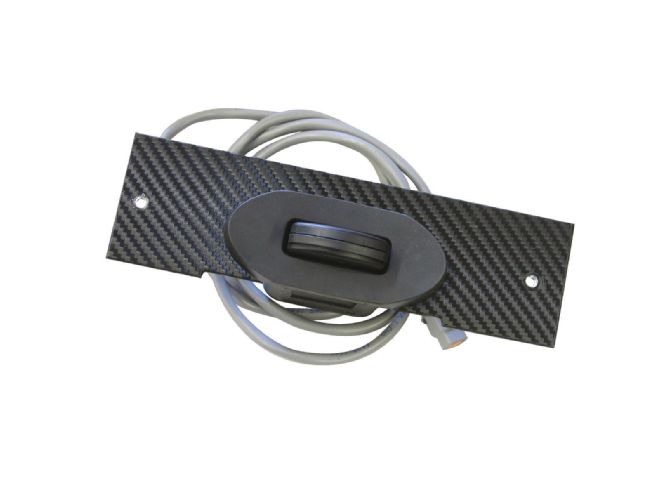 16. To finish the panel, I used black carbon-fiber 3M Scotchprint Wrap Film to cover the bare aluminum before installing the provided face plate.
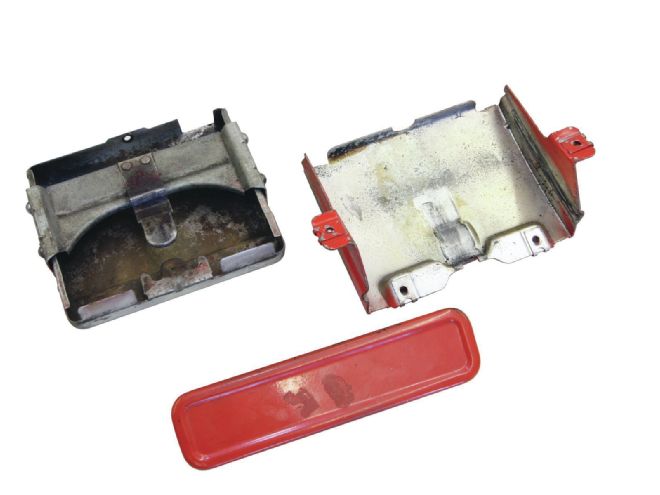
17. I disassembled the stock ashtray by drilling out the rivets that attach the front “door” to the ashtray assembly.
16. To finish the panel, I used black carbon-fiber 3M Scotchprint Wrap Film to cover the bare aluminum before installing the provided face plate.
17. I disassembled the stock ashtray by drilling out the rivets that attach the front “door” to the ashtray assembly.
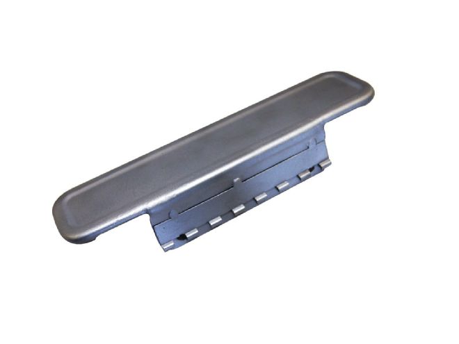 18. Then, I sandblasted the door and tacked one side of a piano hinge to it…
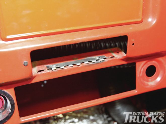 19. …and the other side to the dash.
 20. With the pin in place, I then checked the door to make sure it covers the opening and sits flush.
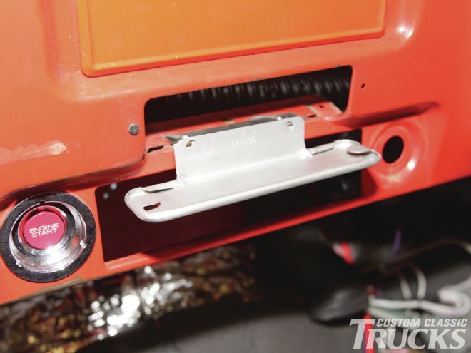
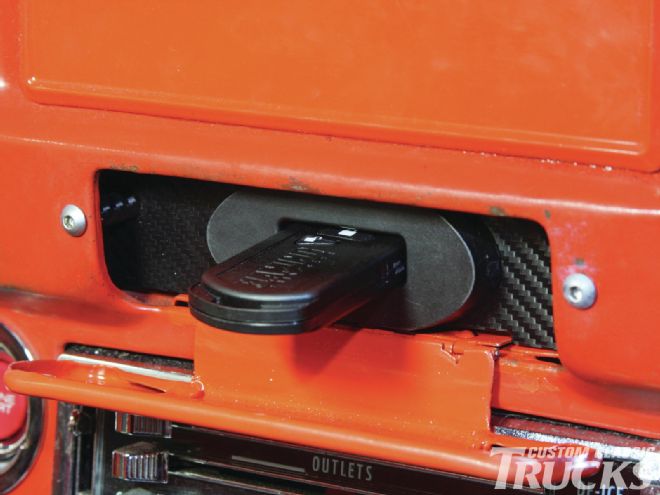 21. Satisfied with the operation of the door, I painted the hinge area on the dash as well as the door, installed the docking station assembly, and installed two high-strength magnets on the door to keep it in the upright position.
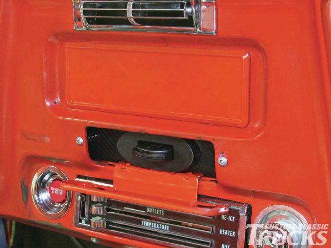
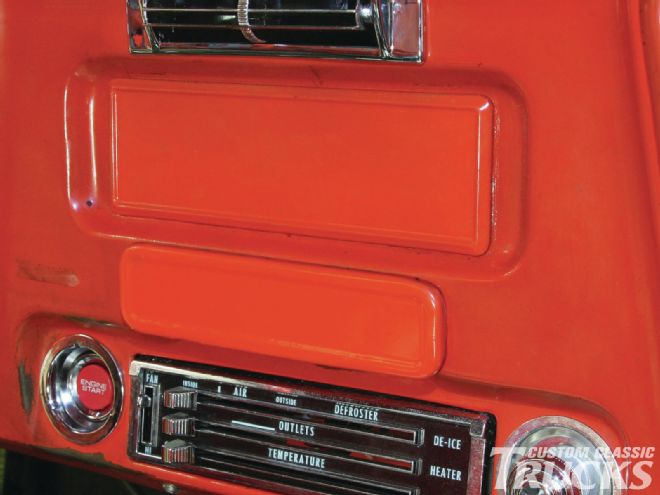 22. With the door shut, it’s impossible to tell that the ashtray has been converted, hopefully thwarting any would-be thieves into locating the ignition source. Without the fob, it’s nearly impossible to bypass the ignition
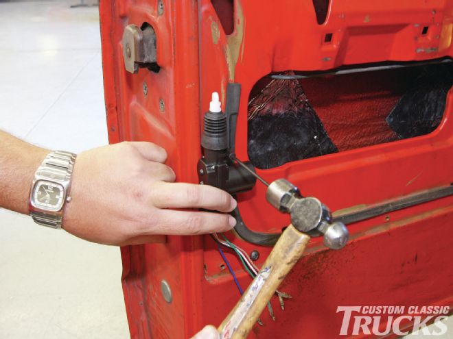
23. The next step is to install the two door lock actuators. You can eyeball the position and mark the holes outside the door frame, just ensure that the panel is clear on the other side and the window is not going to foul on the actuator.
22. With the door shut, it’s impossible to tell that the ashtray has been converted, hopefully thwarting any would-be thieves into locating the ignition source. Without the fob, it’s nearly impossible to bypass the ignition
23. The next step is to install the two door lock actuators. You can eyeball the position and mark the holes outside the door frame, just ensure that the panel is clear on the other side and the window is not going to foul on the actuator.
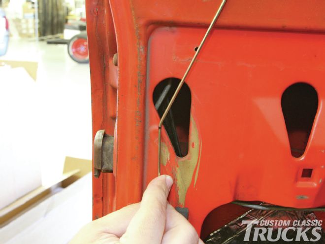
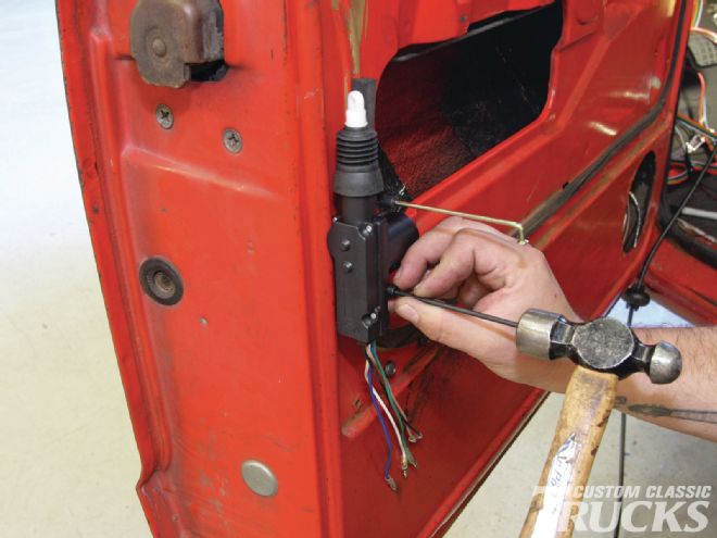 24. Once the top hole was drilled, I inserted the control rod that will connect to the door lock and used it to hold the actuator in place while the lower hole was marked.
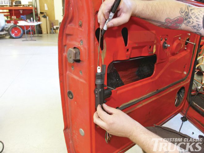 25. Then I marked the control rod where it needs to be bent and trimmed to attach to the door lock.
 26. Note how the control rod is bent parallel to the existing door lock rod inside the door.
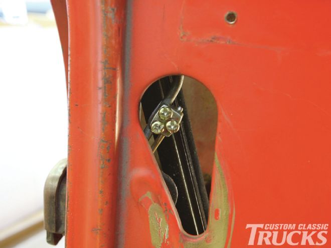 27. With the actuator installed inside the door, the control rod is mated to the door lock rod via the provided rod fixing block.
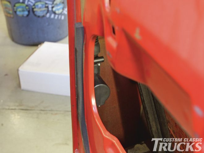 28. The actuator is just visible inside the door.
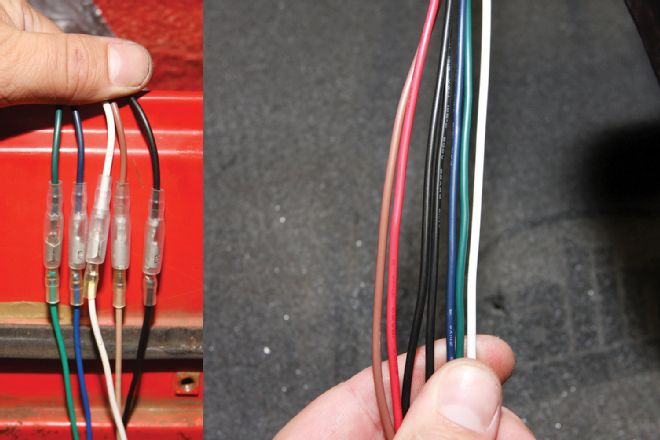 29-30. Wiring the main control lock actuator is pretty straightforward as the wires are all color coded between the actuator and the central control box. The two extra red and black wires are connected to a 15A fused 12V+ source and chassis ground respectively.
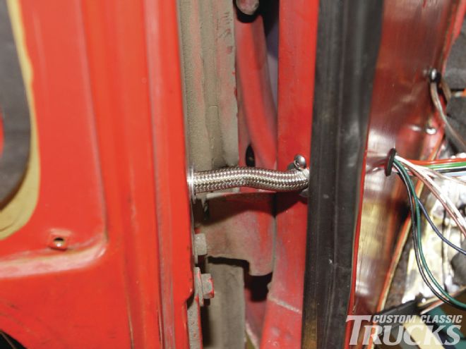 31. These need to be run through a wire loom between the door and the truck cab to prevent the wires from binding. I’m using the same billet wire loom as the electric window kit wires.
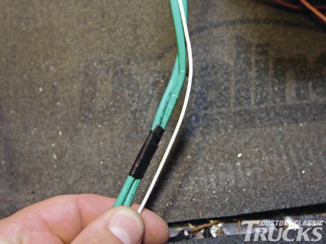 32. These two large green wires and the thin white wire coming from the central control box are not used in our system and can be taped up out of the way.
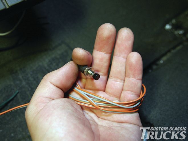 33-34. The door lock kit uses an LED light to signal when the doors are locked and unlocked and is also used during the programming of a FOB in conjunction with the override button.
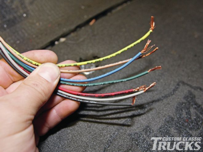 35. Wiring the module and the push button is also simple thanks to the color-coded wires coming from each of the units. Coming from the module, the yellow wire attaches to the accessories relay, the blue wire to the starter relay, and the green wire to the ignition relay, while the brown and gray wires attach to the corresponding wires coming from the switch. The red wire connects to a dedicated 3A fused 12V+ constant hot, while the black is run to a common chassis ground.
 36.The other two wire pigtails on the module mate to the corresponding lead attached to the docking station.
 37. That’s all there is to it! Now with the push of a button, I can enter the truck, slide the FOB in the docking station, push the start button, and we’re off to the races with the security and convenience to match that of any new car.