When hopping up your 1933-34 Ford there are two distinctive looks you can follow: fendered or non-fendered. Either way you have countless options for infusing variables into your build. It's obvious the original designers conceived the body style with all of its sheetmetal in place to accentuate its newfound flowing lines, by removing the fenders and running boards it rethinks their original plan. With your stripped-down car acting as a canvas it's best to step back and study its aesthetic appeal to determine what changes might be right for you.
At the Rolling Bones Hot Rod Shop in Greenfield Center, New York, the styling of post-war hot rods has been raised to an art form where each and every line is studied. When observing a fender-less 1933-34 Ford it's easy to see the reveal lines of the rear quarter-panel and wheelwell fadeaway pulling your vision rearward. This creates the look of a ducktail as well as disturbing the proportions of the wheel fitment to the wheelwell. To address this, Ken Schmidt and Keith Cornell of Rolling Bones came up with a plan to tuck the tail and reconfigure the proportions of the rear wheelwell and quarter-panel's reveal line so they would be in perfect balance. In getting started, Schmidt removed the rear wheel, brake drum, and backing plate, and proceeded with a roll of 3/4-inch masking tape to illustrate how and where the reveal line begins to fade off and outward. With a large section of white cardboard he proceeded to outline the wheelhouse reveal line to create a stock opening template. The template was then cut out with a razor knife and trimmed using a Burr King 12-inch disc sander for perfect curvature. It was then set in place above the axle at 12 o'clock and marked at the reveal line just before the reveal line began its fadeaway. The template was then scored using a razor knife, folded in half, and trimmed to create the perfect radius for the wheelwell. The template was then put back in place and the wheelwell was marked for the required tuck dimensions.
In preparation for the tail tuck, the gas tank was removed and the rear framerails were bobbed. A Hypertherm Powermax 30 plasma cutter was used (while wearing safety glasses) to remove the rear below decklid panel, which was a mounting point for the gas tank cover. Using the rear body reveal line as a guide, Schmidt followed the trimming into the wheelwell. The area was then deburred using a 4-1/2-inch grinder topped with a 40-grit disc. The below decklid outer panel was then unbolted and removed. From the rear of the trunk floor a measurement of 6 inches inboard was taken and marked for removal. A section of steel channel was then clamped in place for use as a guide and a plasma cutter was used to cut out the section. This area was removed to allow ample movement of the rear quarter sections during the actual tuck and will be replaced with fresh steel once the modifications are completed.
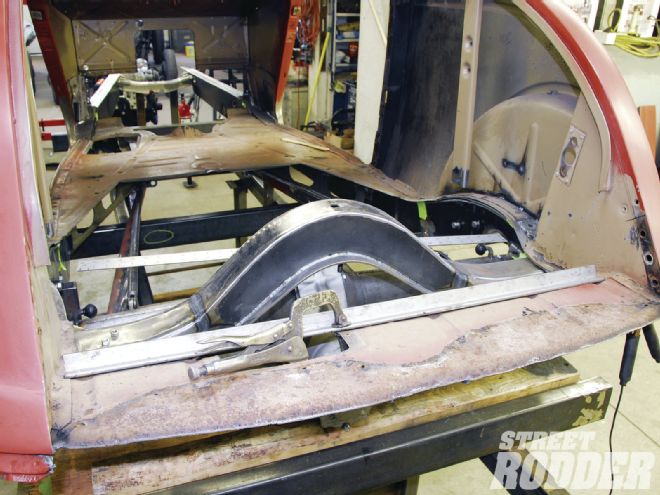
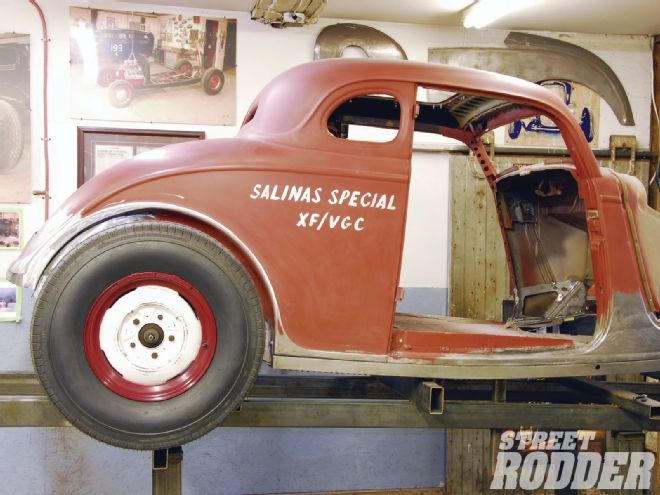
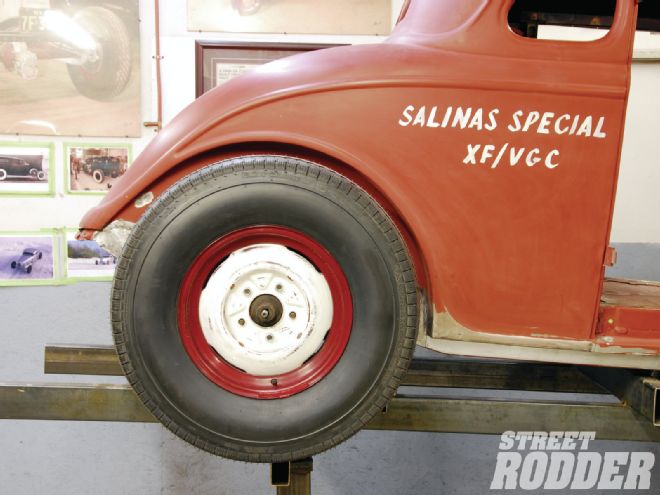 1. With the fenders and running boards removed it’s easy to see the reveal line fadeaway toward the rear of the car. This creates a visual barb where the wheel does not properly fit the wheelwell.
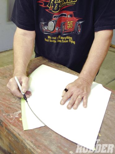
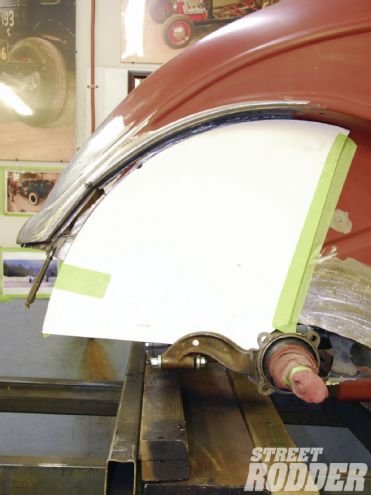
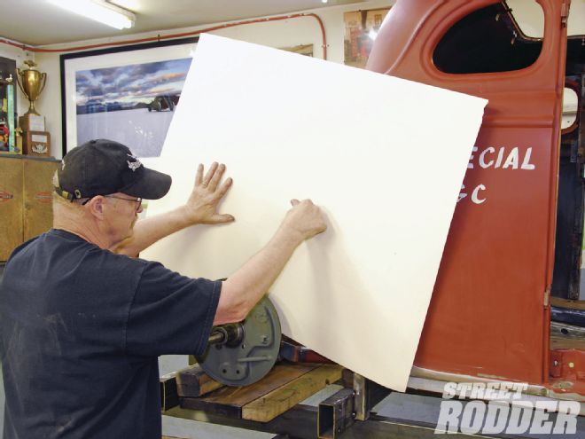 2. Using a sheet of white cardboard, Rolling Bones team member Ken Schmidt outlines the wheelwell reveal lines to create a template of the stock opening.
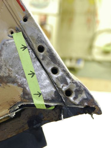
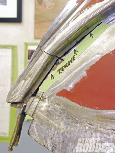
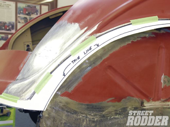
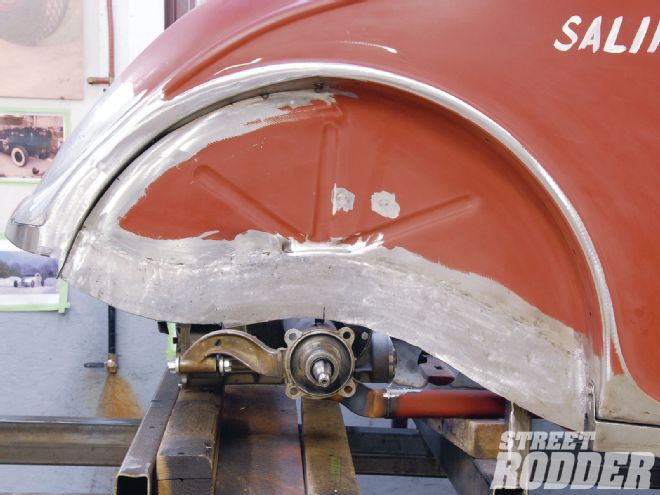
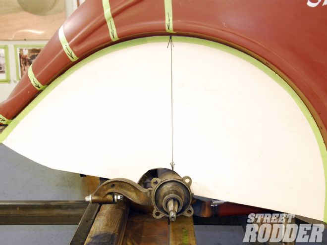 3. With the template cut out and secured you can see the 12 o’clock marking where the reveal line starts to pull away to the left. The arrows indicate where the tuck will be needed to create the perfect wheelwell and reveal line.
 4. The template was cut halfway through at the 12 o’clock mark to allow it to be folded over and create a mirror image of the front half of the wheelwell for a perfect radius.
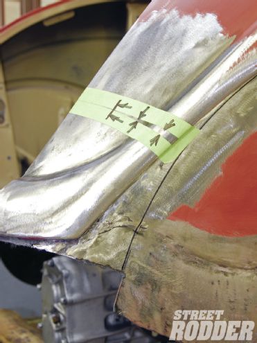
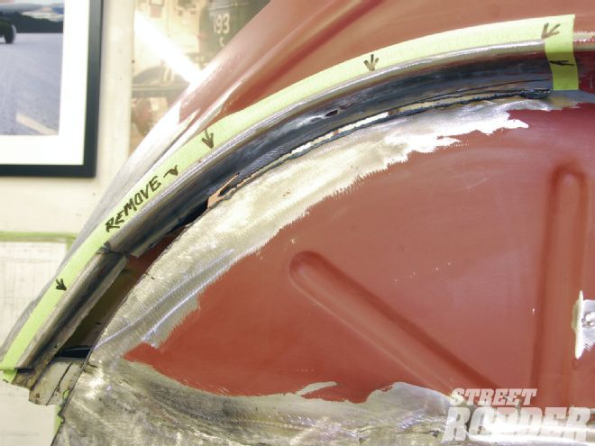
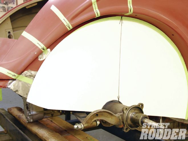 5. With the updated template in place it’s easy to see the amount of work required to effectively tuck the tail as noted by the masking tape markings.
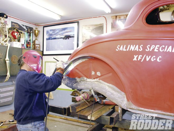
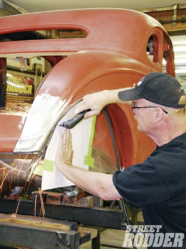
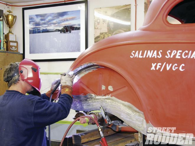
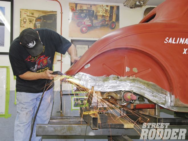 6. With the rear framerails previously bobbed and gas tank removed, Schmidt (wearing safety glasses) used a plasma cutter to cut out the rear, below decklid panel, which was a mounting point for the gas tank cover.
 7. With the area trimmed, a 4-1/2-inch grinder topped with a 40-grit disc will be used to deburr any rough edges.
 8. The below decklid outer panel was unbolted and removed.
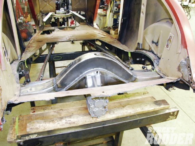 9. Steel channel was then clamped in place to use as a guide to trim 6 inches of the trunk floor with a plasma cutter. This will allow the rear quarter-panel and internal structure movement for the tuck.
To begin the tuck, Schmidt started work on the inner body structure. From the bottom of the inner rear quarter where the below the decklid panel bolts in place, he measured 5-1/2 inches upward from the base adjacent to the mounting holes. The incision was then made with a cutoff wheel. He then measured inboard and marked a graduated 1-1/2-inch wedge pie cut from the base upward and removed the marked area with a cutoff wheel. To allow movement of the panel for the tuck, an adjoining section of the rear sub rail was also removed. Finally a 7-inch measurement was then taken from the outer reveal base up and a 3/8-inch pie cut was marked and removed away using a cutoff wheel. The areas were then deburred and cleaned up. In order for the measurements to work effectively, they were matched to the outer quarter-panel using a square to establish and create a mirror image of the internal pie cut. The area was then marked with 3/4-inch masking tape to confirm the required removal. A cutoff wheel was used to make the incision followed by a matching 7-inch cut complementing the internal one. Finally a graduated 1-1/2-inch pie cut was taken from the exact area on the exterior of the quarter-panel. All areas were then deburred with a disc grinder, topped with a 40-grit disc and flat file.
With the initial incisions completed Schmidt began working the steel on the tail with a body hammer and assorted dollies, gradually moving the panel forward, complementing the pie cuts. This step takes time and patience to gradually move the metal. At this time the rear body panel was bolted back into place. Continuing, there were a number of relief cuts required to relax the steel and allow the tuck to continue movement forward. With the 3/8-inch pie cut closed atop the quarter-panel, a measurement of 2 inches depth with 1-inch-wide increments were marked for relief cuts. The cuts were made using a cutoff wheel and TIG-tacked first to hold them in place. This allowed the curvature of the rear quarter-panel to be worked back into shape. A body hammer and dolly were used to assist in reworking the steel back into shape. The relief cuts were then final TIG welded, with particular attention paid to cool the panel between welds to avoid any metal warp from excessive heat. Finally to allow for additional movement the wheelwell area received a graduated 1/2-inch trim tapering off to 0 inch. The reveal line was then TIG welded. A disc grinder topped with a 50-grit disc was then used to knock down all the TIG welds followed by a flat file to complete the job. A tip from Schmidt was to use a section of welding rod to roll across the quarter-panel to observe any needed adjustments for high and low spots and to follow on the adjustments with a body hammer and dolly, completing the tuck. This step can take time to finesse the panel to perfection.
The final step in completing the job required the reshaping of the wheelwell body reveal arch to give the area a perfect balance. For this Schmidt secured the rear half of the wheelwell template back in place. He followed by marking an area for removal and proceeded using a plasma cutter. The area was then marked using 3/4-inch masking tape for removal of a portion of the inner wheelwell to allow for the re-proportioning of the body reveal. Once the opening was completed, the area was deburred and prepared for the next step. A template was created for the extension of the body reveal arch and inner wheelhouse area and was transferred to 18-gauge steel flat stock. The new section was then TIG welded in place, followed by finessing with a body hammer and dollies to complete the new look. Final grinding and filing left the reworked body reveal arch, inner wheelhouse, and quarter-panel looking factory fresh while completing the look by adding just enough speed to the rear while removing the once present ducktail.
 10. A pie cut to the inner quarter-panel structure was marked 5-1/2 inches adjacent to the rear panel mounting holes with a graduated 1-1/2-inch wedge to be removed with a cutoff wheel.
 11. A measurement of 7 inches was then taken from the outer reveal base upward where a 3/8-inch pie cut was then marked and removed using a cutoff wheel.
 12. On the outer quarter-panel, a mirror image pie cut was established using a square to carry the line from the inner pie cut center. The section was then removed with a cutoff wheel.
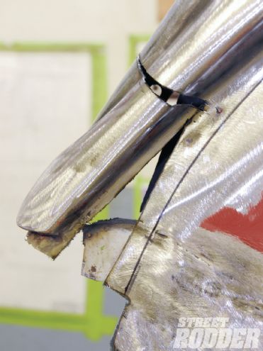
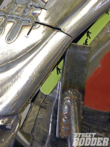
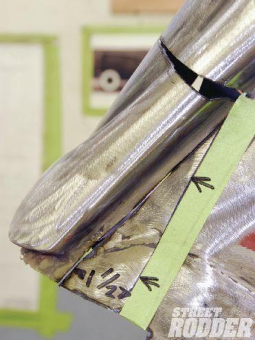 13. Masking tape was used to mark another mirror image pie cut to the outer wheelwell area with a graduated 1-1/2-inch wedge. A cutoff wheel was used to remove the section. Note the tip of the rear sub rail bottom was trimmed to allow the pie cut area to move forward.
 14. Masking tape was used to mark another mirror image pie cut to the outer wheelwell area with a graduated 1-1/2-inch wedge. A cutoff wheel was used to remove the section. Note the tip of the rear sub rail bottom was trimmed to allow the pie cut area to move forward.
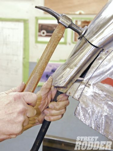 15. Using a body hammer and a dolly, the panel is gradually moved forward into place.
 16. With the rear body panel bolted back in, the quarter-panel is marked for a number of relief cuts 2 inches deep and 1-inch across. This allows the metal to regain its stock curvature.
 17. Team member Keith Cornell then TIG-tacked the initial incisions in place to prepare for the relief cuts.
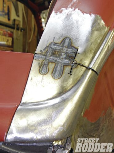
18. Here you can see the completed relief cuts with final TIG welding now in place.
17. Team member Keith Cornell then TIG-tacked the initial incisions in place to prepare for the relief cuts.
18. Here you can see the completed relief cuts with final TIG welding now in place.
 19. To allow for the tuck’s continued movement, the inner wheelhouse was marked for trimming 1/2 inch from the left to a tapering of 0 inch.
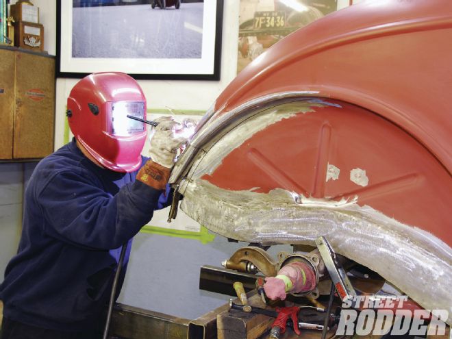
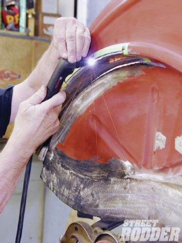
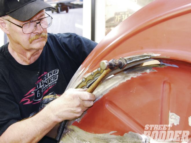
 20. A homespun slap hammer was used to wedge the reveal lines together to allow TIG welding to hold the tucked line in place. A hammer and dolly were then used to make the panel perfect.
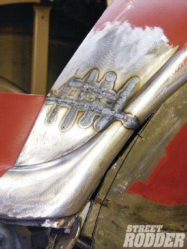 21. Here's what it looks like after the TIG welding is done.
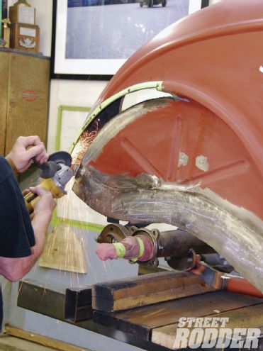
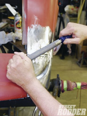 22. A 1-1/2-inch disc grinder topped with a 50-grit disc was used to work down the TIG welds followed by a flat file to smooth everything out.
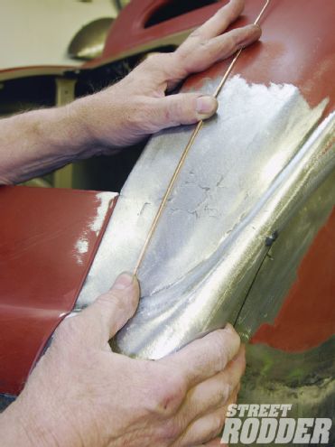 23. A welding rod was then used to roll across the panel to locate any high or low spots and to fine-tune the panel with a hammer and dolly.
 24. With the tuck portion complete, the rear half of the template was set back in place to map out additional trim needed for the reworking of the body reveal lines.
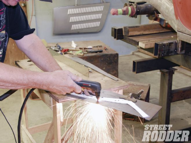
 25. Using the template as a guide, a plasma cutter was enlisted to remove the noted area.
 26. A tapeline was set to the outer reveal line to mark the section of the inner wheelhouse area to be removed. A new section will be created to complete the updated proportions.
 27. Using a plasma cutter, the area was carefully trimmed.
 28. The area was then cleaned and deburred using a 4-inch circular grinder topped with an 80-grit disc. It was then finished off using a flat file.
 29. Here you can see the cleaned up inner wheelhouse area awaiting the next step.
 30. A cardboard template was created for the extension of the body reveal arch and inner wheelhouse area.
 31. The template dimensions were transferred to 18-gauge flat steel stock and cut out using a plasma cutter. The edges were then deburred and filed clean for installation.
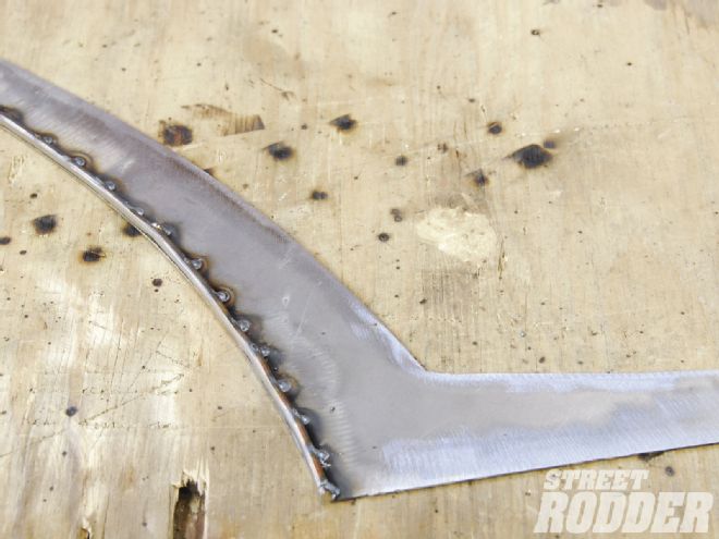 32. A section of welding rod was tacked in place to the new inner reveal curve for added strength and to aid in the two panels in being joined together to create a new stock-appearing side reveal roll.
 33. The new panel was then TIG tacked in place. It was then finessed by Schmidt using a combination of body hammers and dollies till the desired curvature was achieved.
 34. With the new curvature completed, the panels were final TIG welded into place. The area was then ground smooth and finished with a combination file.
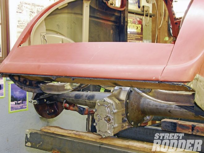
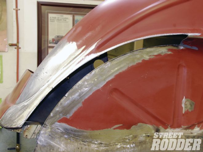
 35. Here you can see the completed tail tuck and reworking of the wheel arch and reveal area.
 36. With the rear wheel mounted back in place it’s easy to see the significant difference made to the overall look to the rear side of the car with its newfound speed added to the body lines.