As much as I preach about having a plan when building a hot rod, I still seem to do a bit of wandering during the course of a build. Last month I was working on the rear suspension, installing the Panhard bar, etc. Since then, I've moved on to the engine prep and dress-up, and last weekend I began locating the body and bed and fabbing my mounting points for each. I guess it's because there's so much involved in a ground-up build like this that I see things that need to be done everywhere I look. That said, I think I'm really getting a handle on things, as I'm actually seeing the light at the end of the tunnel. At this point (after completing the chores I'm about to outline in this installment), the only chassis chores left to do are installing the Chassis Engineering Inc. front shock mounts, and fabbing and locating the mounting plate for my Speedway Motors reversed Corvair steering box.
Before I move on to this month's look at my progress, I thought I'd take a moment to address a few questions I've received from you folks via e-mail. First off, yes, I'm well within budget so far. The luck of getting my hands on a free engine and transmission saved me about $600-the amount I'd allotted myself for a well-running used combo. I'm confident that the project will come in at budget ($10K), or even possibly a bit below. Next, I've been asked about specifics on the frame kickups. The front kickup measured 3 inches from the top of the forward 'rail to the bottom of the trailing 'rail-so, the measurement from the bottom of the 'rail ahead of the kickup to the top of the 'rail behind the kickup is a total of 9 inches. Measured the same way out back, the kickup is 7 1/2 inches-making the measurement there 13 1/2 inches. Another question I've been asked more than once was in regard to my use of the miter saw for cutting metal instead of wood. What I've done is pick up a few (quite a few, actually) 10-inch Norton metal-cutting discs from my local Home Depot store. They're normally found in the tool aisle near the chop saws, etc., and they work extremely well. Any brand will work (they don't have to be Norton), but the only thing you want to make sure of is that the saw you use doesn't exceed the maximum recommended rpm for the wheel you use. I do know, though, if the saw rpm is markedly slower than the disc's maximum, the disc wears out pretty quickly. That said, the setup works extremely well.
OK, now let's get on with it. Last weekend I tackled locating and attaching the bed and body to the chassis. Since the frame was homebuilt and lengthened from the original A dimensions that I halfheartedly used as a baseline, I did need to pay attention to body location while making sure I left ample room for my somewhat lengthy six-cylinder engine while still centering the bed over the rear axle line. Once located and marked, the rest was less than rocket science, so let's take a look.
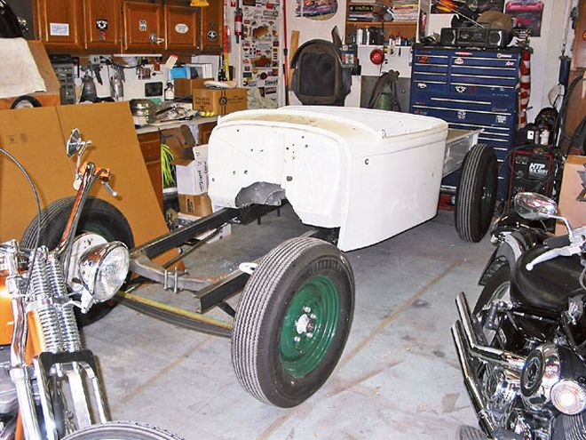
Here's a shot of the nearly completed roller; last weekend I decided it was time to fab up my body and bed mounts, getting me one step closer to sewing up the chassis.
I started out by mocking the bed into place, centering the wheels in the bedsides.
Next I grabbed my pals Nick and Jesse and they gave me a hand lifting the cab into place on the framerails. With a bit of maneuvering, I located the cab with about an inch of space between it and the bed front, which left me with adequate room ahead of the firewall for engine fitment.
Since I'm not one for the complicated or exotic, my mounts are simple and do the job. I used a couple of lengths of 7/8-inch square tubing that were trimmed to fit flush with the bottom mounting flange on the bed, centered so the bed fit on the 'rails squarely, and then clamped in place.
The rearmost length of tubing was located below the rear frame crossmember and left full length.
The front length of tubing spans the framerails as shown here but was trimmed at the inner edge of the 'rails at each side after welding.
Once the mountings were welded to the framerails, the bed was again set into place and mounting holes drilled through the bed mounting flanges and the mounts at the same time. Drop in a quartet of bolts washers and nuts, and the bed is in place.
With the bed handled, it was on to the body. This shot is looking down at the floor supports and the framerails. Rather than just drilling through the supports and into the 'rails and tapping the 'rails to accept mounting bolts, I decided to fab some mounts that would be welded to the 'rails instead.
All I did to make the mounts was take a couple of 4-inch lengths of 2x3x.120 rectangular tubing and cut them in half from corner to corner on the 1-inch side of the tubing. This gave me four wedge-shaped pieces of 2-inch channel that formed the mounts.
With the mounts ready for installation, I marked the 'rails before removing the body.
The wedge-shaped mounts were then located at the marks on the 'rails and then welded onto the outside of the framerails at each marking.
Once they were all welded into place, the body was again lowered into place and the body and mounts drilled at the same time to accept the mounting bolts. It was an easy way to mate the body and bed to the chassis. All that's left is to cut a bit of rubber sheeting to serve as insulators between the body and mounts, and it's on to the next step.
It was brought to my attention (thanks, Ron) that I failed to mention an important step during the construction of the parameter frame-reinforcing the kickups. As this image shows, it is important that each of the welded seams is reinforced by a method called fish plating. The inner and outer seam of each intersection should be reinforced both inside and out by the addition of a plate welded across each seam. This reinforces the joints and will ensure adequate strength of the unions while under stress. Welding the 'rail tubing alone only allows one outer wall to accept all the stress, while fish plating distributes the stress to additional structure, reinforcing the chassis and adding additional strength.
Chassis Engineering
319-643-2645
www.chassisengineeringinc.com
HTP America
800-USA-WELD
www.usaweld.com