With the current boom in custom engine bays and the constant search for new ways to hide, tuck, or eliminate every potential eyesore under the hood, enthusiasts (often dubbed trend setters or innovators in the Honda community) have come up with some interesting ideas. Some are good, and others are, well, not so good. A new wave of cooling and braking modifications have recently garnered quite a bit of attention by those looking to take their custom bays to a whole new level. As with any trend or movement, some jump in headfirst without considering the pros and cons. To help shed some light on what to expect, and how to do things safely, I'm going to touch on these two subjects and let you decide for yourself if these mods are right for you.
 |
Engine Bay Customizing - Engine Bay Dynamics
|
Engine Bay Customizing - Engine Bay Dynamics
Tucked radiators
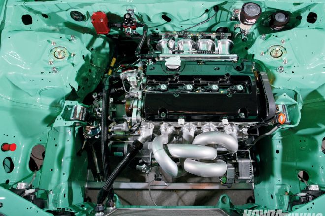
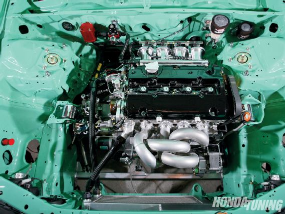
Let's start with what seems like the easiest modification first: the radiator tuck. Now before you order that shiny new piece, there are a few things you should know right away. What you are essentially doing is placing the radiator further under the radiator support, hiding it from a person's view as they eye the engine bay. A few things happen when you move the radiator out of its original mounting location. The first is that the fill location is either now eliminated, or far too low for proper use. Honda put the fill neck at the highest point in the cooling system for a specific reason: to allow the air bubbles to escape efficiently. If it's lower than the highest point, you can run into major issues. An improperly bled cooling system can lead to high coolant temperatures, eventually turning into a busted head gasket. Choosing how you place the coolant fill point can make or break your entire setup. While helping a friend build his Prelude's custom cooling system, we placed the fill point up and through the actual radiator support with the cap sitting just above the highest point in the system. Other systems I've designed have placed the fill along the upper hose, between the head and the radiator, or even off of a welded-on pipe that leads straight back toward the firewall. In the end, it doesn't really matter how you design the fill point, as long as it's placed at the highest point in the system, and it runs somewhere along the upper cooling hose. There are products currently available that mimic the design in my Project CRX. Check out K-Tuned.com for their new line of billet parts.
 |
Arnel's EH engine bay features a rywire.com custom tucked radiator, and if you look closely (arrow), you'll notice the filler neck just in front of the distributor. Also note the custom hard lines from the deleted booster on the left side of the photo.
|
Arnel's EH engine bay features a rywire.com custom tucked radiator, and if you look closely (arrow), you'll notice the filler neck just in front of the distributor. Also note the custom hard lines from the deleted booster on the left side of the photo.
This leads to the next, most overlooked portion of the system: the pressure overflow cap. Your cooling system is designed to have a relief mechanism that allows excess coolant to be displaced if coolant temps become too high. The same system allows the coolant back in if necessary. Some of the setups I've seen use no overflow at all. This can cause high pressure in the system, resulting in head gasket damage or even worse. In regards to the water line, we often rely on -16 AN (Army/Navy) fittings due to their inner diameter sizing, and ease in bending compared to the larger -20 AN fittings. These can be pricey; expect to pay about $30 for each hose end, and about $10 for a weld-on fitting. Working with these fittings can be quite difficult, so be sure to check manufactures' recommendations on assembly to ensure a leak-free cooling system.
 |
Big Mike and Rywire teamed up to create one of the slickest tucked radiator setups around on Mike's Prelude. Note the fill point and cap that protrude through the radiator support.
|
Big Mike and Rywire teamed up to create one of the slickest tucked radiator setups around on Mike's Prelude. Note the fill point and cap that protrude through the radiator support.
The final piece to the puzzle is the fan. With a tucked radiator's low-profile from top to bottom, proper fan sizing needs to be addressed. When running a "pusher" fan, one thing to remember is that the fan must not overlap the front surface of the radiator! Mounting incorrectly can direct some of the airflow under and over the radiator fins, rather than through them, as was intended. This can lead to severe overheating, or worse. The custom radiators I design typically measure about nine inches tall, and a single nine-inch fan can be used, or in some cases, dual nine-inch fans. If all of these issues are properly addressed in the beginning, you can have a safe, tucked radiator setup that can be driven on a daily basis.
Brake line tuck
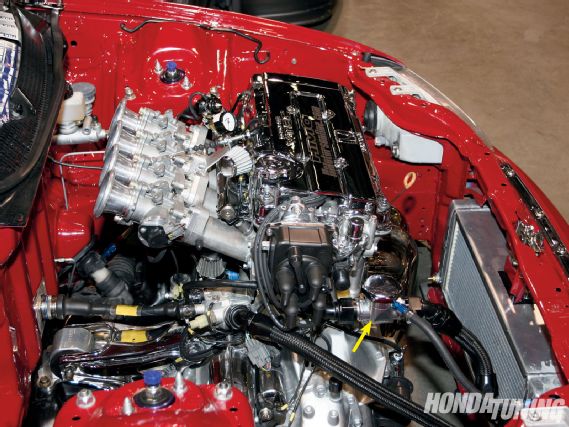
Another popular trend popping up these days is the proportion valve relocation, or the "brake line tuck." In my eyes, this is one of the most difficult jobs when it comes to properly tucking a bay. But if it's done correctly and safely, a successful brake line tuck can give you incredible results. Basically what is done here is the brake line proportion valve is relocated under the car, inside the cowl, or (the most popular) inside the cabin, behind the firewall. Placing this unit out of sight helps drastically with the engine bay's gutted theme, and even makes it easier to swing a wrench without all the factory brake lines getting in your way.
|
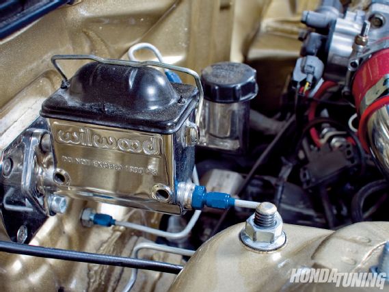
A Wilwood setup complete with custom hard lines
Using proper parts when doing this is a must, and I would not suggest this being done any other way. I currently offer a complete brake line proportion valve relocation kit on my website: Rywire.com. The kit consists of all the proper AN fittings and properly crimped preassembled brake lines to accomplish this job in just a few hours. All of the lines are -3 AN-sized bulkheads, hose ends, and stainless line made from the highest quality parts available. All that is required on most kits is simply drilling a few holes for the bulkheads to secure through the firewall, the rest is tightening the fittings firmly so there are no leaks whatsoever.
One popular myth is that having uneven line lengths will effect breaking in a negative way. If this myth was true, Honda would not have designed the '88-'91 Civic/CRX chassis with extremely uneven lengths from the factory.
Check it out some time-the front right wheel line is about ten inches long, while the front left line is just over five feet! Another myth is that using soft lines in the brake system is unsafe. My opinion of this is that if you are using good quality crimp-on AN fittings and stainless line, you should have no problems whatsoever with this technique. However, like anything else, when using soft-line outside of the cabin, dirt and debris will eventually wear out the line right where the fitting and the line meet. Hard-lines on the other hand should last a lifetime when used properly. I would suggest the line choice be based on skill level and tools available to the installer. If you have never bent or flared a line in your life, hard-line might not be the right choice for you.
Booster Delete
For a number of years, front-wheel drive racers have been ditching their brake boosters to shed excess weight and run foot braking only on the front two wheels. Plates were being made to run a single piston Wilwood or Tilton master cylinder pressurizing brake fluid to the front wheels, and eliminating the proportion valve altogether. As you can see, this method could be extremely unsafe on public streets. The problem lies in the factory Honda pedal ratio of nearly 3:1. Pedal effort becomes extremely hard, and the car will stop slower than with the booster assisting. Boosters work by using your engine's vacuum, and applying it to your brake pedal. This boosted pressure allows the driver to stop their car without having monster bodybuilder calves.
 |
Rywire.com
|
Rywire.comRyan "Rywire" Basseri owns and operates Rywire.com, an online source for wiring conversions, harnesses, sub-harnesses, custom braking kits, and much more. He's the "go-to guy" for some of the more impressive and cutting edge builds in the industry, and has been known to go to great lengths in order to help his clientele.
You may be asking; "why would Wilwood develop such a useless product?" Their master cylinders have a specific purpose, and that is to be used on their own pedal assemblies. The Wilwood and Tilton pedals are the complete package and offer the ultimate solution. These pedals can be found in many off-road race trucks, drag cars, circuit racing cars, and every other race-prepped vehicle in the modern racing world. They can allow greater feel for the driver when breaking, giving them the edge over the competition. The first huge upgrade over Honda's factory pedal ratio is that the pedal assemblies actually come with a much more aggressive ratio of 6:1. This helps drastically with pedal pressure, and helps make up for the booster not being there.
The pedal will still feel stiffer than a Honda Civic fresh off the dealer's lot, but that's to be expected. The aftermarket pedal set will also offer dual master cylinders; one for each pair of wheels. This allows the option for further brake tuning with the ability to run uneven bore sizing on each master. And lastly, the pedal set will give the driver the option for the bias shaft bar to be placed on the pedal assembly itself. This adjustable bias acts like an adjustable proportion valve, giving the drver even more tuneability while on track.
Some of the new Honda "trend setters" have been using these brake booster eliminator plates mated to Wilwood single outlet master cylinders and factory proportion valves. What must be done here is to use the single outlet from the master cylinder and "T" it into both inlets of the proportion valve running all four wheels at once. Factory master cylinders have dual outlets and a tandem diaphragm design to drive fluid to the front and rear wheels independently. If the factory master cylinder happens to fail, you will only loose the front or rear braking, not all four wheels. If the Wilwood single diaphragm fails when running it this way, you will lose front and rear at the same time. The possibility of failure and the stiff pedal are two very large drawbacks to running this setup on the street. My personal suggestion to people on the fence about running the product this way is to steer clear and let the vacuum assist you safely.