Technical
Engines work best when the right things happen at the right time. For instance, when ignition spark happens too late, you might embarrass yourself on the dyno; when it happens too soon, you might end up with a scenic view of the inner workings of your block. The relationship between an engine's cams and its crank is no different. The rise and fall of the pistons has to synch up with the opening and closing of the valves. This is even more important to pay attention to once aftermarket cams, adjustable cam gears or other mismatched components, each with their own tolerances, are factored in, as well as once an engine's deck or cylinder head have been resurfaced. Even the slightest tolerance change or amount of material removed will alter the distance between the cams and the crank, which, in turn, will alter their relationship with one another and disturb cam timing. All of this makes it even more important to properly degree your cams.
 |
Adjusting Camshaft Degree - Camshaft Degreeing
|
Adjusting Camshaft Degree - Camshaft Degreeing
Cam degreeing-or "zeroing in" cam timing-is the only way to ensure that your cams are performing optimally and that your piston-to-valve clearances are what you think they are. It's also the only way to ensure that your valves open up all the way at precisely the right time. It's a process that should be performed whenever cams are swapped or an engine's been rebuilt-before visiting the dyno. You'll need adjustable cam gears to do it, as well as a degree wheel, a dial indicator, and some basic hand tools.
But don't assume that cam degreeing has anything to do with dialing in your adjustable cam gears to some predetermined setting. Your cam gear manufacturer has no idea how much your block's been surfaced, how many times your head's been milled, or who manufactured your cams. Neither does the kid on the internet whose, incidentally, got "the same setup" and assures you that a couple of degrees of advance on your intake cam is exactly what you need. To be sure, cam degreeing is more than simply the twist of a couple of adjustable cam gears based off of where the cam gear manufacturer says "zero" is. Degreeing cams ensures that the cams are in their correct position-for your engine-nobody else's. The guesswork's eliminated.
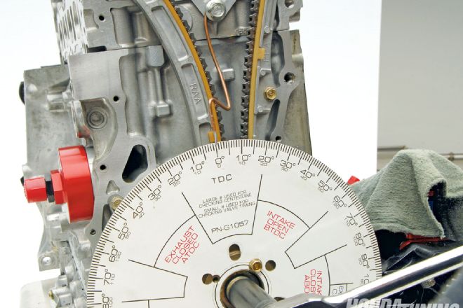
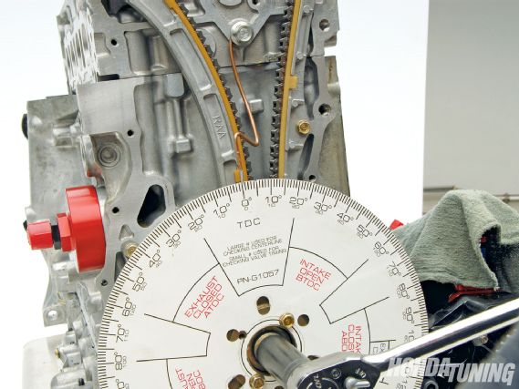
1 Visually set the Number One piston to TDC (top dead center), remove the crank pulley, and fasten the degree wheel to the crank with its TDC mark pointing up. The process is easiest with the engine on a stand but can also be done with it under the hood.
 |
Adjusting Camshaft Degree - Camshaft Degreeing
|
Adjusting Camshaft Degree - Camshaft Degreeing
2 Cut off a six-inch piece of welding rod or a metal coat hanger, bend it into a "J" shape, and sharpen its long end to a point. Slide a bolt through its "J" and fasten it to the engine, somewhere below its cam gears, allowing the rod's sharpened end to point toward the degree wheel's TDC mark. Position the rod close to the wheel, without touching.
3 When degreeing cams, never rely on the engine's pulley, block, or timing belt/chain cover markings to locate TDC. Variables like block height and piston dwell often make such methods inaccurate. Instead, use the piston-stop method to determine precisely when the piston's reached its absolute highest point and the middle of its dwell. Rotate the crank so its Number One piston is near the bottom of its bore and thread a piston-stop into its spark plug hole. You can fabricate your own piston-stop out of a spark plug or anything that threads into the spark plug hole and hits the piston just before TDC. Next, rotate the crank in its normal direction of rotation-counterclockwise for most older four-cylinder Honda engines, clockwise for most newer ones-until the piston contacts the piston stop, and note the wheel's degree value corresponding with the pointer. Rotate the engine the opposite direction until the piston contacts the piston-stop again and record that value. TDC is located exactly halfway between those two values.
 |
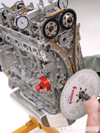
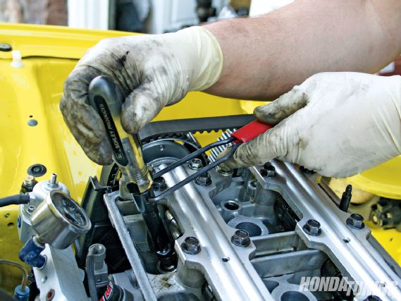
Installing and being able read the degree wheel with the engine in the car is challenging but can be done. To fit it to this H22A engine in a '92-'95 Civic chassis required removing the crank pulley, left-side mount, timing belt cover, and lowering the engine as much as possible just to clear the frame.
|
Installing and being able read the degree wheel with the engine in the car is challenging but can be done. To fit it to this H22A engine in a '92-'95 Civic chassis required removing the crank pulley, left-side mount, timing belt cover, and lowering the engine as much as possible just to clear the frame.
4 Without moving the crank or degree wheel, reposition the pointer to line up with the degree wheel's halfway point you just recorded. Now, remove the piston-stop and rotate the engine in its normal direction of rotation, this time aligning its TDC mark with the pointer. Be sure it's dead-on, and don't disturb it. You've now accurately located TDC and, chances are, it's not where your timing cover and crank pulley said it should be.
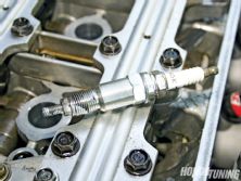
5 Position your dial indicator's tip on one of the Number One piston's intake valve retainers. Don't position its tip on the rocker arm as the rocker ratio will distort the results. For an accurate reading, be sure that the dial indicator's needle is parallel to the valve. You may need to fabricate some sort of base that bolts the dial indicator to the cylinder head to position it appropriately. Close the valve lash all the way, and ensure that the valve is closed completely by checking that the rocker pad is positioned on the camshaft's base circle, not its lobe.
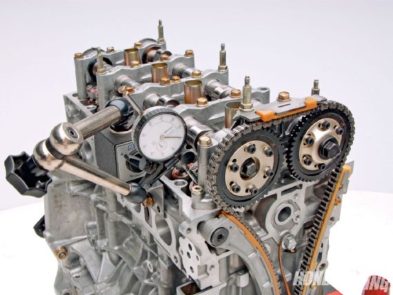 |
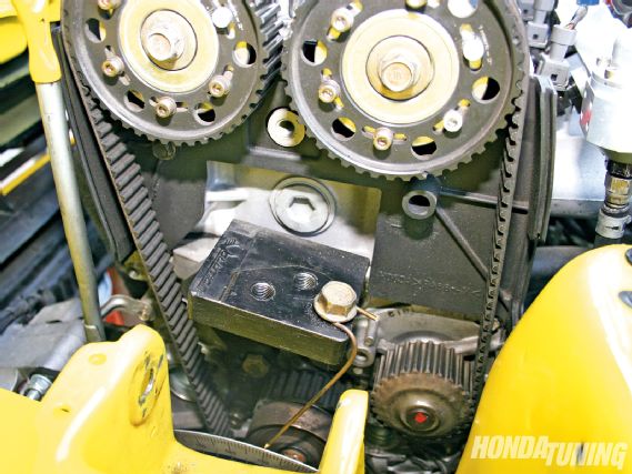
Finding a suitable and sturdy location for the dial indicator isn't easy. Mount it securely for accurate results.
|
Finding a suitable and sturdy location for the dial indicator isn't easy. Mount it securely for accurate results.
6 Rotate the crank in its normal operating direction. Observe the dial indicator's reading as its respective valve opens. Keep rotating the crank until the pointer lines up with your cam's specified peak lift degree value, also known as its intake or exhaust centerline, depending on which cam or lobe it's referring to. This information can be found in some service manuals for OEM cams and from the manufacturer for aftermarket ones. If you overshoot your mark while rotating the crank, continue for another full rotation until everything lines up. Never rotate the engine in the opposite direction since a tensioner will only align its cams and crank appropriately when spinning forward.
 |
Close the valve lash completely on the intake and exhaust valves from which you'll be measuring lift.
|
Close the valve lash completely on the intake and exhaust valves from which you'll be measuring lift.
7 With the degree wheel positioned at your cam's peak lift degree value, loosen your adjustable cam gear bolts and rock the cam back and forth until the dial indicator shows its valve is at full lift. You'll know it's at full lift when the gauge displays its numerically smallest reading. Ensure that the crank hasn't moved, tighten the adjustable cam gear bolts, and rotate the engine two complete revolutions, this time monitoring when the dial indicator once again displays peak lift. Observe the degree wheel to ensure that it's once again at your cam's advertised centerline. If it isn't, start over.
8 Repeat the process for the opposing exhaust cam lobe, using the appropriate exhaust peak lift specifications.
9 If you made any sort of adjustments, you'll want to re-mark your adjustable cam gears to reflect their new "zero" reference points. For example, if you retarded your intake camshaft one degree to coincide with its peak lift, then "minus one" degree is your new "zero."