Since we worked on the head and valvetrain in our budget B-series build this month, we figured now would be a logical time to cover a camshaft basic. One of the keys to making power is to properly set camshaft timing; in other words, when valves open and close in relationship to the position of the piston and crankshaft is critical to the performance of the engine.
The process of properly setting the camshaft position is referred to as "degreeing the cam." Many beginner tuners mistakenly believe that to degree cams means setting the cam gears at a certain position such as "+1 intake and -2 exhaust." Though this information may be useful at times, these settings may not be accurate on all motors.
For example, when the deck of a head or block is machined, it will retard the cam timing. So the cam gear setting method may only apply to engines using the same type of cam gears with exact same head and block heights. This also assumes that the given cam gear settings are the correct location for the cams.
The most accurate way to set camshaft position is to properly degree the cams. This way you can be sure the cams are in the right position regardless of engine variations, deck heights, and cam gear marks. The method we are proposing is a simple way for setting cam positions using peak lift measurements. Cam degreeing can also be used to check valve opening and closing positions, durations at various lifts, and peak lift measurements.
 | Helpful Tip 1
When degreeing a camshaft, make sure that you rotate the crankshaft in the direction the engine normally runs. If you over shoot the position the crankshaft is supposed to be in, do not rotate the engine backward. It will throw off your numbers because the tensioner only works properly in one direction.
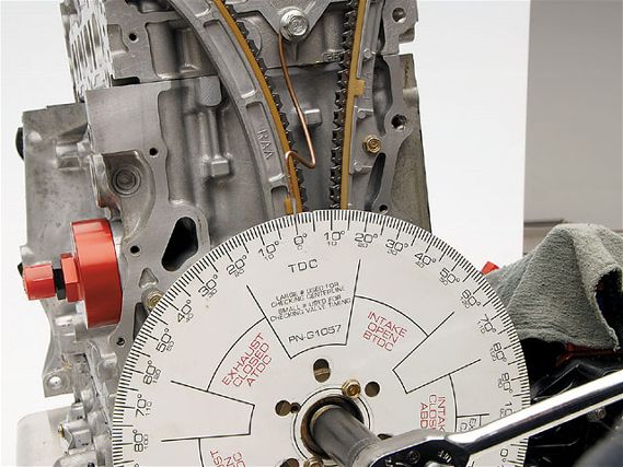
Step 1: Install a degree wheel onto the end of the crankshaft, and bolt a pointer onto the block. The pointer can be a sharpened piece of welding rod or coat hanger that can be bent to change the position of the pointer. Rotate the crankshaft to top dead center, or TDC, for piston no. 1. You can use a dial indicator inserted down the spark plug hole or the piston stop method; the piston stop method is more accurate. When the crankshaft is at TDC, move the pointer so it points to TDC/0 degree on the degree wheel.
Step 2: Set up the dial indicator with the tip on the retainer, NOT the rocker arm. To get an accurate reading, it is important to make sure that the axis of the indicator is parallel with the axis of the valve. Make sure the rocker is on the base circle of the camshaft; in other words, make sure the valve is completely closed, and zero out the dial indicator. We recommend that you degree the cam with the lash set at 0.000-inch.
 | Helpful Tip 2
If you are having a hard time finding the centerline because the cam dwells at peak lift, you can take a reading of the degree wheel when the cam reaches max lift less than 0.003 inch before and after peak lift. The middle of those two positions will be the centerline.
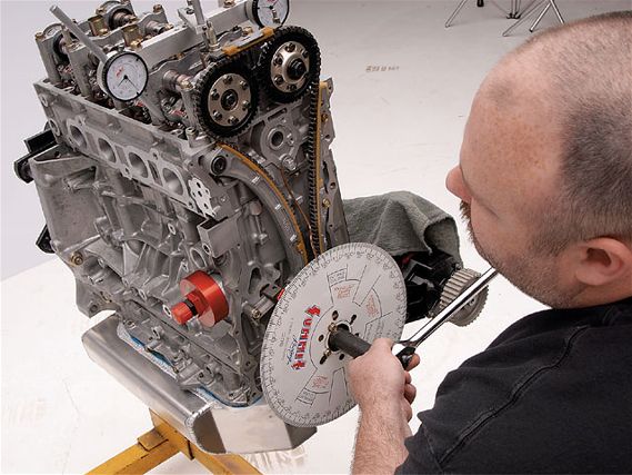
Step 3: Rotate the crankshaft. When the cam starts to open the valve, the dial indicator will show the amount of valve lift. Rotate the crankshaft and stop when the pointer is pointing at the specified peak lift/center line position. Loosen the cam gear bolts and rotate the camshaft until the indicator is showing that the cam is at peak lift. Tighten the cam gear bolts. Rotate the engine two more rotations, stopping when the dial indicator reaches peak lift, look down at the degree wheel to make sure the position of the crankshaft is in the correct location. If not, repeat step 3.
Step 4: Move the dial indicator to the other side of the head, and repeat steps 2 and 3. When peak lift positions of both the intake and exhaust cams are set in the proper locations, the cams are considered to be degreed in.
 | How to Degree Camshafts - Camshaft 101
CAMSHAFT DEFINITIONS
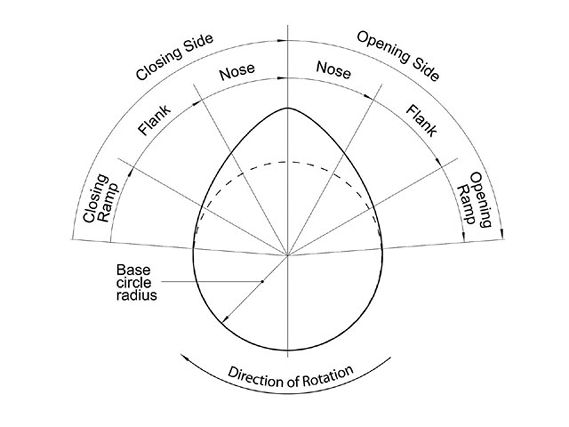
When discussing camshafts, enthusiasts often get confused with the terminology used to describe the various parts of the camshaft. This diagram and these definitions should help most people better understand camshafts and their related terminology.
Ramp
The textbook definition of ramp is the section of the cam from the base circle to where the valve physically begins to open, or finishes closing. It is also commonly referred to as a clearance ramp; or in other words, the part of the cam lobe where the camshaft will close up the initial tappet clearance (lash) and the tappet/follower will make initial contact (on the opening side) or end its contact with the camshaft (on the closing side). Skunk2 defines ramp as the portion of the profile from the base circle to the point of maximum valve acceleration. Skunk2's Fast Ramp Technology helps the valve go from zero to maximum acceleration as quickly as possible and still maintain superior valvetrain stability.
Flank
This is defined as the end of the ramp section to the point where the valve reaches maximum velocity. We frequently hear people talk about "aggressive ramps" when they are actually trying to describe the flank and how quickly the valve is opening. It is important to find the balance between opening the valve too quickly and not opening the valve quick enough. If the valve is not opened quick enough, "area under the lift curve," the airflow is not optimized. If the valve is opened too quickly the camshaft may run off the tappet, and it will become difficult to slow the valve down enough as it goes over the nose.
Nose
Nose is defined as the section between the maximum velocity on the opening side and maximum velocity on the closed side, or rather the section of the cam where the valve spring forces are keeping the valvetrain from separating from the cam surface. Controlling valve accelerations over the nose is critical to preventing valve float and high-rpm valvetrain stability. Skunk2 Amax Technology allows the company to design the flank and nose section of the cam to maximize area under the curve and still maintain valvetrain stability.