 | Compound Forced Induction, Part 2 Turbocharging The Ultimate "Mr6" Power-Adder Test-Bed - 1991 Toyota MR2
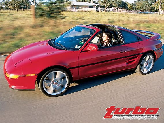
 In the last installment, we stuffed a big 1MZ-FE 3.0-liter Toyota V6 into our project '91 MR2 Turbo. We then installed a TRD Eaton-based blower kit and then bitch-slapped the V6 to 325 hp with the help of a MoTeC engine management system.
In Part 2, we will yank the supercharger, add a custom air-water turbocharging system, recalibrate the MoTeC M-48 computer, then hammer it on the dyno turbo with both glamour power-adders making boost-compound forced induction style.
Historically, staged forced induction has been used for super-high boost applications where the required pressure ratio for a single compressor is too high for reasonable thermal efficiency, or where sufficient boost is impossible with one compressor. Achieving, say, 50 psi boost with one turbocharger may require an enormous centrifugal compressor section and may result in excessive charge heating and significantly increased intercooler loading-and could be in great danger of surging, depending on total engine air consumption.
With twin staged compressors, an equal amount of air might be supplied to the same engine at the 50 psi level with greatly reduced heat of compression due to improved thermal efficiency, with the added benefit of improved spool time and responsiveness.
Our plan was not necessarily to run extreme levels of total boost (though we wanted that potential); it was to combine turbocharging with supercharging to get the best of both technologies. The great strength of a root-type Eaton supercharger is it provides instant boost when you open the throttle, avoiding turbo lag entirely.
 | Compound Forced Induction, Part 2 Turbocharging The Ultimate "Mr6" Power-Adder Test-Bed - 1991 Toyota MR2
 A positive-displacement root-type supercharger provides linear increases in pumping volume at the cost of maximum boost, achieving reasonable thermal efficiency in the 1 to 8 plus psi range (though inferior to that of the centrifugal compressor in a turbocharger or centrifugal blower).
For our application, a big turbocharger would take up where the Roots blower left off, compounding 5 to 10 psi Stage One supercharger boost to virtually any level of combined boost required-with reasonable thermal efficiency.
Perhaps our biggest compounding challenge was going to be the following: How much boost could the 1MZ engine tolerate without detonating on 93-octane premium pump gasoline? Remember, the supercharger is located inside the intake manifold, and can't, for all practical purposes, be intercooled.
Corky Bell, owner of Bell Experimental Group in San Antonio, Texas, and author of technical books on turbocharging and supercharging "Maximum Boost" and "Supercharged!", calculated that an Eaton supercharger running 5 psi boost (.33 pressure ratio) ideally provides a temperature increase of 8.5 percent; applied to an ambient temperature of 100 degrees F, the unit would heat the 100-degree air to 148 degrees. Correcting for the Eaton running as much as 62-percent efficiency, the blower will actually raise 100-degree ambient air to 177 degrees.
A maximum-performance MR6 requires the intercooled turbo sub-system of the compound forced-induction system compensate for the blower's thermal heating by keeping charge air at or below ambient temperature at 15 to 20 psi boost (prior to supercharging). All this with up to 500 whp worth of airflow and negligible pressure drop through the intercooler.
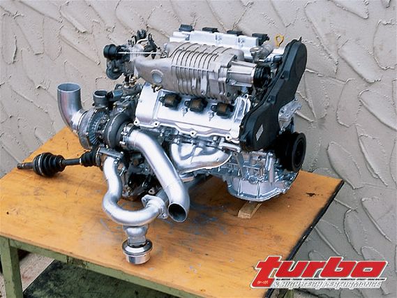
 | Here we see the full compound forced induction 1MZ V6 installed in the MR2. The engine's V design means there is plenty of room for a turbo and the block mates to the transaxle without modification. " After much consideration and test fitting, the turbo system, seen here, was fabricated by Alamo Autosports.
 For this, we were going to need a giant custom air-to-water intercooler. An air-to-water design would allow us to optimize the layout of the air cooler separately from its water-cooling radiator (particularly valuable on a mid/rear engine vehicle).
We decided to locate the intercooler in the MR2 trunk behind the rear engine firewall. Alamo Autosports siamesed two air-air cooler cores and boxed them with sheetmetal to contain liquid coolant. The goal was zero pressure drop at 500 whp with high efficiency.
Sizing turbos and blowers correctly is critical to extracting the maximum performance when compounding two compressors in a series as a compound or staged system.
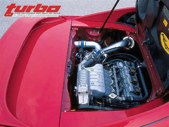
 | Here we see the full compound forced induction 1MZ V6 installed in the MR2. The engine's V design means there is plenty of room for a turbo and the block mates to the transaxle without modification. " After much consideration and test fitting, the turbo system, seen here, was fabricated by Alamo Autosports.
 We consulted with forced-induction experts Bob Norwood and Corky Bell. Bell ran some pressure-ratio and density-ratio equations and suggested some criteria for the right compressor and turbine for turbo-assisted supercharging. Norwood discussed compounded engines he'd worked with in the past, and made suggestions on compressor trim and turbine A/R.
We also consulted with Majestic Turbo in Waco, Texas regarding selection of specific turbocharging equipment. The TRD positive-displacement blower would knock out full boost the instant the throttle opened, and this would immediately generate enhanced exhaust energy and heat to spool a turbo. Of course, to achieve 500 whp, you'd need to make more like 575 to 625 hp at the crankshaft, which at a ratio of 10 hp per pound of air implies roughly 60 pounds of air per minute airflow required from the turbo compressor. The smallest Garrett-type compressor that'll possibly achieve this airflow is a GT-61 trim unit.
Centrifugal compressor performance is fairly predictable using compressor maps, but it can be difficult or impossible to predict turbine performance on a particular engine without a certain amount of testing. Unfortunately, it's largely turbine performance that determines the onset of measurable boost.
Corky Bell pointed out that 70 to 80 percent of the energy required to drive a turbine comes from the heat in the exhaust rather than the pressure. The energy that can go down the shaft to drive the compressor is a function of the absolute Turbine Inlet Temperature to the fourth power, minus the absolute Turbine Outlet Temperature to the fourth power.
Since the temperature drop through the turbine nozzle can easily be 200 degrees, there is prodigious heat energy available to drive a centrifugal compressor.
So we see that the turbine energy available to do work is dependent in a small way on exhaust pressure, and in a big way on exhaust heat (which is why insulating or coating exhaust plumbing on the way to a turbine can yield dividends in faster turbine response. It takes great energy to overcome the inertia of a turbo and to accelerate it extremely rapidly to full working speed.
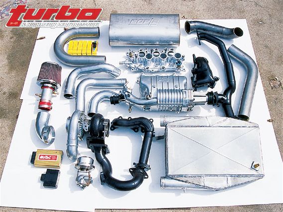
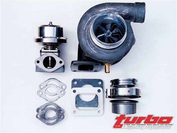 | Majestic Turbo of Waco, Texas, supplied the critical turbo system components for the compound MR6; a T-76 turbo, Majestic Deltagate dual-ported wastegate, turbine exhaust V-band ring and clamp, gaskets, and flanges.
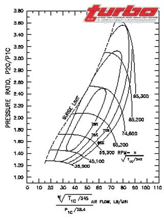
 What's more, because centrifugal compressor air flow increases exponentially with compressor speed, the compressor must be turning 30,000-40,000 rpm before it's capable of significant pumping at all. A T-76 compressor, for example, can begin to make boost at as low as 36,000 rpm, whereas a T04E-60, for example, requires as much as 46,000 rpm shaft speed to make viable boost pressure.
Majestic Turbo supplied a honkin' huge T-76 turbocharger to make boost and a delta-type Racegate to limit total maximum boost delivered by both the blower and the turbo. The initial turbine setup was a Majestic P-trim wheel in a .81 A/R housing. Majestic's T-76 is a large turbo capable of delivering 90 lb/min of air at a pressure ratio between 2.6 and 3.2-good for supplying enough air for as about 900 horsepower. One would not necessarily expect such a big air pump to deliver much low-end boost, but the idea was to let the blower deliver the low-end boost.
Fabricating the Turbo SystemOne fine day in the late spring of 2002 we drove the supercharged MR6 onto a lift at Alamo Autosports in Arlington, Texas to begin construction of the turbo conversion-and immediately developed some new muscles hefting the T-76 into various possible placement locations in the Toyota's engine room.
Initially, we considered locating the turbo in the upper engine compartment above the transaxle and piping exhaust to it directly from both exhaust banks. We eventually decided to locate it behind the transaxle to the left of the engine near the rear-bank exhaust.
This made fabricating the exhaust system a much easier task for Alamo, while providing enough room behind the V6 for a 3-inch turbine discharge pipe that would plumb into a muffler and/or catalytic converter with passenger-side entry.
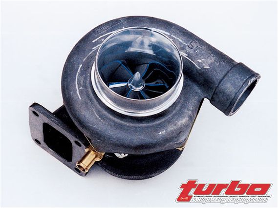 | The compressor is a Majestic T-76, capable of 90 lb/min of air-that's 900 hp. The compound-system turbine A/R was a .81, which worked well with the blower, but was sub-optimal in turbo-only configuration.
 The location placed the compressor conveniently close to the rear firewall, intercooler and throttlebody. Later, we would reinforce critical areas of the header-to-turbo plumbing with gussets and TIG welding for maximum strength.
After mocking up and tack-welding the basic turbo plumbing, we pulled the 1MZ-FE V6 engine for final turbo system welding and for machining operations on the block to install fittings to supply pressurized oil to the turbo center section and drain oil back to the sump.
In the final mock-up and installation of the turbo system, Alamo techs welded a V-band discharge fitting to the T-76's turbine, and carefully constructed a mandrel-bent exhaust system with Borla stainless tubing and super-high-flow muffler. With the exhaust system in place, we then bolted the Majestic Deltagate to a flange welded onto the side of the collector-to-turbine inlet pipe.
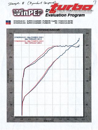 | Dyno 1: Compound-supercharged MR6 made 330-rwhp at 5700 rpm on the Norwood Autocraft dynamometer, and 300 lb-ft torque from 4000 rpm on up with the wastegate open.
 While dyno testing the supercharged-only MR6, we had pushed the stock injectors to their fuel-delivery limit and beyond. With the stock 288cc injectors operating at 100 percent of duty-cycle under MoTeC control, the only option to deliver more fuel had been to increase fuel pressure using a Bell Engineering variable-rate-of-gain fuel pressure regulator. We had finally achieved nearly 260 rwhp on the Norwood Dynojet with the stock injectors.
Now, with bigger power in mind, we obtained a set of giant 630cc peak-and-hold injectors from Bosch. These injectors are low-resistance 6-amp units with a form-factor similar enough to the stock 1MZ's 288s that-with O-ring changes-they're usable with the stock 1MZ fuel rail and lower-manifold injector bosses. At rated fuel pressure, these injectors can deliver sufficient fuel for as much as 750 hp.
The stock MR2 Turbo fuel pump runs out of capacity at roughly 60 psi, just above 400 flywheel horsepower, and requires boosted voltage (for example, from a Kenne-Bell Boost-A-Pump) to deliver additional fuel. In lieu of boosting the OE pump, an auxiliary in-line fuel pump could be added or a high-capacity in-tank unit could be substituted.
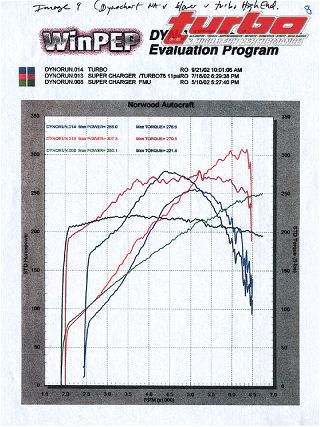 | Dyno 2: Blower only, turbo only, and compounded dyno runs. The blower's torque curve is almost flat, while the turbo-only run is hump shaped. The Compound dyno run pushed torque up another 50 to 100 lb-ft above the blower and hung on to 6500 rpm. The big T-76 turbo was optimized well with the blower, but for turbo-only operation, Majestic later changed to a lower-inertia assembly and smaller A/R turbine housing.
 Compound-Supercharging Test and Analysis
Compounded behavior was simple: With the wastegate referenced directly from the compressor section of the turbo, the turbo began making additional boost and torque above and beyond that of the supercharger as low as 2300 rpm. From this point, torque and boost increased in a smooth, linear fashion until the wastegate opened at 4000 rpm and stopped the boost increase at 5-psi turbo boost, 5 to 10 psi total boost (depending on wastegate setting).
If we kept the wastegate closed, boost and torque headed directly for the top of the dyno chart. In one memorable early runaway dyno pull, the MR6 managed to hit 300 lb-ft rear-wheel torque at 4000 rpm before Bob Norwood backed off the throttle.
It became apparent the forced-induction and fuel-delivery systems vastly exceeded the mechanical capacity of the 1MZ V6 powerplant. And when a 15-psi dyno run lifted the rear head just enough to produce a slight, brief outbreath of coolant steam, we realized that further gains demanded better head fasteners and wire O-ringed cylinders with copper head gaskets to prevent catastrophic head gasket failure. We also knew the stock pistons and connecting rods would not be long in this world at 15 psi boost..
We contacted Wiseco to order custom super-duty pistons built with the stock 10.4:1 compression ratio, but designed such that the piston crowns could be machined to reduce compression while maintaining sufficient thickness. We also began looking for a set of custom 1MZ rods or possibly some super-duty performance rods that could be modified to fit the 1MZ crankshaft.
 | The T-76 is designed to generate big power in the mid- to top-end, leaving the blower to act as a spool-up kit at lower engine speeds.
 With these super-duty parts in the engine, we were confident the 1MZ would survive a lot of boost. But we also recognized that sooner or later the stock 1MZ valve springs would float and that valves and intake ports and cam profiles that flowed well on a 200-hp, all-motor engine were going to be a major restriction on a 500-plus hp compoundsupercharged engine.
In the meantime, we were eager to get some road-test results without grenading the engine, so we settled for a wastegate setting and a "Compound" MoTeC calibration that reliably delivered a reliable 425 flywheel horsepower.
In approximately 8,000 miles of driving, ranging from south Texas in the scorching heat of summer to northern California in the chill of fall nights, we found the compound-supercharged system completely reliable and streetable. Bottom-end felt big-block massive yet top-end developed with a turbo rush. The compound super-turbo MR6 even had its own sound.
According to Jerry Magnusen, who designed the 1MZ TRD blower kit, when a compound turbocharger is operating at full-howl-forcing tons of boost downstream into the TRD blower-turbo boost actually begins to drive the blower's rotor assembly like exhaust gases driving a turbine, actually putting power back into the supercharger drive belt.
And, indeed, we observed that as the turbo component of boost spooled up above 5-psi boost, the blower whine of the Eaton fades and what you hear is purely the whisper of turbo power. A lingering and unresolved question is what the overdriving turbo does to the parasitic drag of the supercharger if turbo boost is pushing energy back into the blower belt.
Turbo-Only Testing and Optimization
After we'd driven the modified car around Texas, we decided it was time to test the MR6 in turbo-only mode.
As you might expect, in each of the possible permutations of power-adder modes (none, turbo only, blower only, compounded with both) there were unique areas of the MoTeC air-fuel map the engine would encounter that weren't reachable in certain other modes.
For example, the turbo makes lower boost at full-throttle and 2000 rpm than you'll ever see with the supercharger at the same engine speed, yet the optimal turbo calibration in this range is not precisely the same as the N/A engine. The loading required to drive the supercharger has an effect, as does the exhaust backpressure of a turbocharger.
All of which meant that Bob Norwood had some dyno work to optimize turbo-only performance after we pulled the blower.
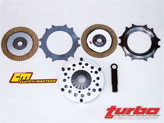 | A Clutch Masters multi-disc Kevlar clutch assembly was designed for smooth operation on the street and track. Pedal effort is light, yet the clutch system is capable of extreme clamping force.
 The first turbo-only dyno runs were U-shaped; the T-76 with .81 A/R was sluggish in the bottom end, and turbo-only torque did not surpass blower-only torque until 3500 rpm. At 4500 rpm, the turbo-only torque temporarily surpassed the compounded torque, and by 5700 rpm, turbo-only torque had fallen below that of blower-only torque, neither of which we'd expected to see.
With the blower off the MR6, we drove 1,000 miles from Dallas to Tucson, Ariz., in the turbo-only configuration, at which point we reinstalled the blower and continued on a road trip to L.A., after which we again removed the supercharger for a drive to Silicon Valley. We eventually returned 2,000 miles to Austin, Texas, uneventfully.
Throughout the trip, all systems were up to the best abuse various magazine editors and I could extract from on-highway flogging. The Clutch Masters multi-disc clutch performed equally well stuck in L.A. freeway traffic or under hard, race-type flogging.
Although the turbo was sluggish in the 2000 to 3000-rpm range, the 1MZ motor is not sluggish, and people who drove the turbo-only car loved the low-end all-motor torque combined with the rush of additional power and torque as the turbo spooled up to make 10 psi boost in the mid-range.
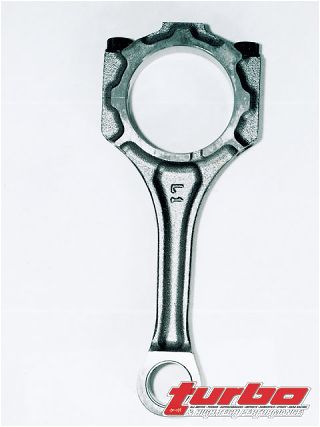 | Stock 1MZ connecting rod The stock rods held up through double the stock boosted power, but we had no special wish to discover exactly when they do break.
 Various people advanced theories for the loss of turbo torque in the higher-rpm ranges. One was that turbine energy was insufficient to drive the big T76 compressor wheel in this range. Another was that we had some kind of mismatch between the turbine and compressor in terms of available exhaust energy vs. turbine speed. Yet another was, for some reason, ignition energy was degrading in the upper speed-density ranges (coincidental to the removal of the blower).
Without installing a turbo-shaft tachometer on the T76, we were shooting in the dark. But, in any case, we decided to focus first on improving turbo-only low-end spooling, and see what this did to the disappearing torque above 5000 rpm. We began looking for ways we might improve turbo-only spool-up in the 2000 to 3000-rpm range without devastating compounded performance in the higher end.
After considering a compressor change to a smaller wheel to reduce inertia and speed up the turbocharger, Majestic recommended swapping turbine housings to a .70 A/R and reducing spooling inertia with a patent-pending Majestic fastener in place of the standard nut on the turbine end of the turbo shaft.
In fact, the .70 housing is a twin-entry unit, and we are currently considering redesigning the exhaust feed to maintain separate exhaust pipes from the two banks all the way to the twin-entry turbine housing.
In the meantime, Ignition Solutions shipped us a set of six Plasma-direct performance coils, which can be installed as coil-on-plug devices, or with plug wires. According to Ignition Solutions, the Plasma Direct replacement ignition coil is designed "with built-in booster technology to amplify secondary spark current by 100 percent (two times as much as OEM) and release about four times as much energy at the initial moment of spark."
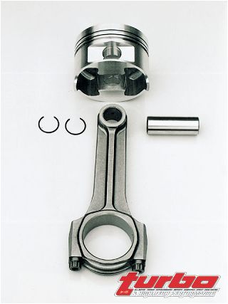 | Better forged connecting rods and Wiseco forged pistons with full-floating pins are designed to survive as we pump up the compound boosted power to levels in the 600 to 900 hp range.
 As of the writing of this article, we have not yet generated dyno results with the new ignition and turbo equipment. We are looking forward to further development of the turbo-only and compounded engine configurations, to measuring power losses in the blower-only configuration, to measuring turbine power losses of the turbocharger due to backpressure or other factors in the turbo-only configuration, to logging turbine speed, and to measuring temperature rise and intercooling efficiency associated with the turbo and the supercharger at various levels of boost.
We expect soon to get dyno runs of the turbo and compound engine at 1-psi increments to 20 psi with 93-octane Texas pump gasoline and/or unleaded race fuel. Stay tuned.
Pros & Cons of Roots Blower, Turbos & Compound SuperchargingRoots Advantages
* Instant boost on throttle application
* Good low-rpm boost (with by-pass valve) zero charge heating at idle and high-vacuum cruise
* Good and linear volumetric efficiency
Roots Disadvantages
* Excessive heating at higher boost (over 8-10 psi) due to reversion-pulsed turbulence of non-compressed air from the supercharger encountering higher-pressure previously compressed air in the intake
* May be inconvenient or impossible to intercool
* Robs some of the power it produces from the crankshaft
* Can be noisy
Turbocharger Advantages
* Excellent thermal efficiency to high-boost pressures
* Not limited to crankshaft speed (may lag behind, but can surge ahead with sufficient exhaust energy)
Turbo Disadvantages
* At least minimal delay in onset of boost
* Boost inaccessible at lowest rpm ranges
Compound Advantages
* All of the above
* Supercharger produces excellent low-rpm exhaust energy to spool turbo
Compound Disadvantages
* May be inconvenient or impossible to intercool supercharger section