My Project S14 has been in its “build” process for the past six years of ownership and I have—for the equivalent number of years—said my next step was motor work. It wasn’t until recently that I was able to retire the car from daily duty and put some serious thought into the direction I want to go with the car. The decision to turn the car into a fully race-prepped one allowed me to consider more serious engine modifications.
Jim Wolf Technology (JWT) offers a variety of cams available for the Nissan KA24DE motor. The S1 cams were chosen, as they were not too mild and not too aggressive. I took the car over to Corner 3 Garage in Lake Forest, CA, to install the JWT S1 cams and degree them with their adjustable cam sprockets. To see the power gains from this mod plus a few other goodies, check out Power Pages (Dec. ’11 issue).
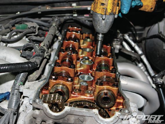
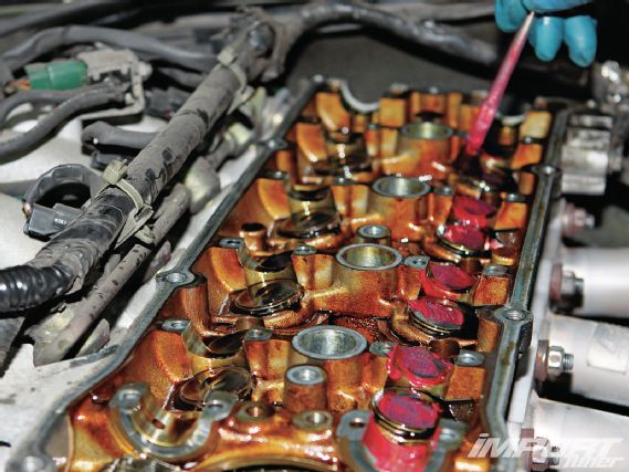
01 Remove the valve cover to start the process of swapping the cams. To begin, the engine must be set to top dead center (TDC) for cylinder number one. Here you can see that the cam lobes on cylinder number one are showing that both valves are not closed—the exhaust valves are closed but the intake valves are open. With this, we know the engine is not set at TDC on this cylinder.
 |
Nissan 240SX Cam Upgrade - Build Log
|
Nissan 240SX Cam Upgrade - Build Log
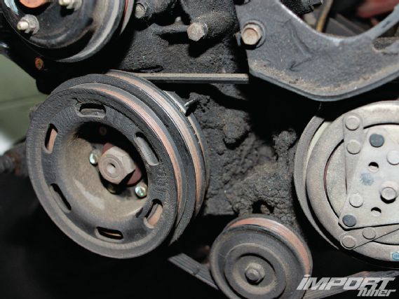
02 Set the engine to TDC. TDC is when the piston is at the very top of its stroke. When the crank pulley indicator is at TDC, it will either be for cylinder number one or number four.
 |
Nissan 240SX Cam Upgrade - Build Log
|
Nissan 240SX Cam Upgrade - Build Log
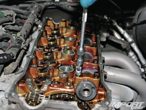
03 Here is a close-up of the crank pulley and the indicator pointing to the TDC mark. In this case, it is the second mark from the left side when facing the engine. Look at the camshafts and make sure that the engine is set to TDC for the number one cylinder and not TDC for the number four cylinder. You can do this by looking at the camshaft and verifying that both camshaft lobes for the number one cylinder are facing outward. After this is done, look at the alignment mark on the cam sprockets and mark the link on the timing chain that it is in line with. Make sure the marking is made without gouging or scoring the chain. One way to do this is by cleaning the oil off the link that you intend to mark and using paint or a marker.
 |
Nissan 240SX Cam Upgrade - Build Log
|
Nissan 240SX Cam Upgrade - Build Log
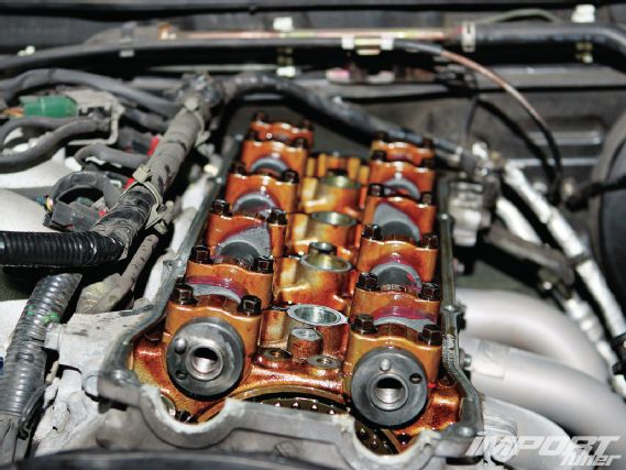
04 In this photo, you can see that the lobes on cylinder number one are facing outward, indicating that the intake and exhaust valves are closed. The next step is to remove the bolts on the front of the cam sprockets by holding the camshaft with a wrench. There are flats on the camshaft where you can place your wrench.
 |
Nissan 240SX Cam Upgrade - Build Log
|
Nissan 240SX Cam Upgrade - Build Log
 | Nissan 240SX Cam Upgrade - Build Log
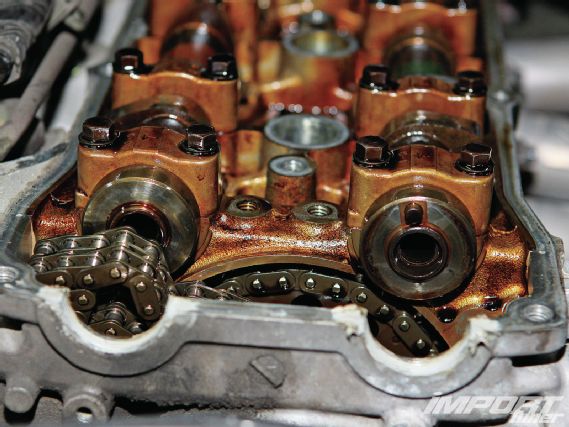
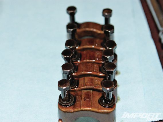
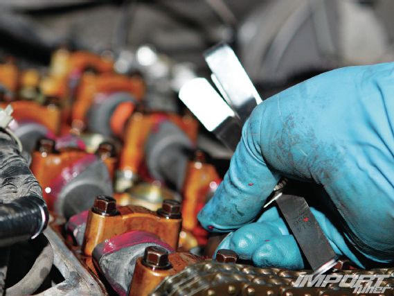
05 Remove the cam caps on the exhaust cam. After removal of the caps of the exhaust cam, arrange them exactly the way they came out of the engine. It’s extremely important that they’re not mixed or turned around as this could cause binding of the camshafts. At the top of the caps, there is a stamping from the factory indicating its position and direction.
 |
Nissan 240SX Cam Upgrade - Build Log
|
Nissan 240SX Cam Upgrade - Build Log
 | Nissan 240SX Cam Upgrade - Build Log
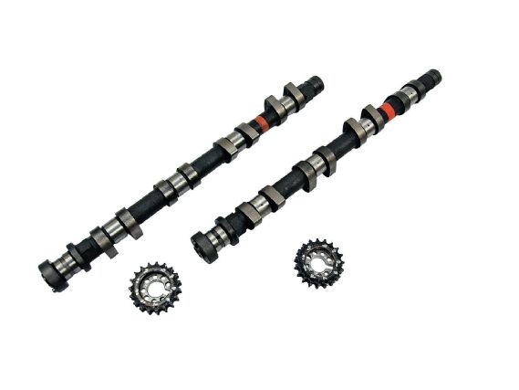
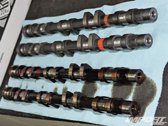
06 The factory intake and exhaust cams (bottom) have both been removed and are shown here in a side-by-side comparison with new JWT cams (top). If you look carefully, the profile of the lobes on the JWT cams are noticeably bigger.
 |
Nissan 240SX Cam Upgrade - Build Log
|
Nissan 240SX Cam Upgrade - Build Log
 | Nissan 240SX Cam Upgrade - Build Log
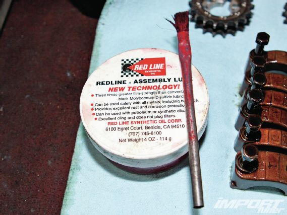
07 Before installing the new camshafts, it is recommended to lube the areas that they will be contacting. We used Redline’s Assembly Lube.
 |
Nissan 240SX Cam Upgrade - Build Log
|
Nissan 240SX Cam Upgrade - Build Log
 | Nissan 240SX Cam Upgrade - Build Log
08 The new intake and exhaust cams are both settled in, and the cam caps have been torqued down according to spec (80–104.2 in-lb). Be sure to install the cams the same way the stock ones came out. Rotating them to line up after installation would potentially bend the valves. When tightening the caps, thread the bolts in by hand first and then tighten more in small increments. Work evenly from the front to the rear and back and forth toward the middle cam cap. If one cap is tightened all the way down while others are loose, you will place a bending load on the camshaft causing it to potentially break in half.
 |
Nissan 240SX Cam Upgrade - Build Log
|
Nissan 240SX Cam Upgrade - Build Log
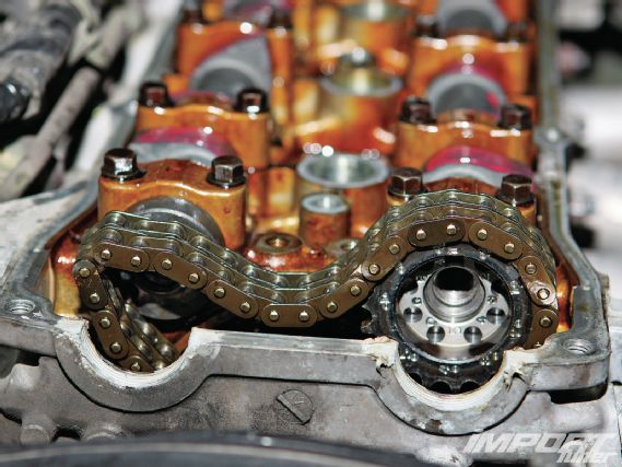
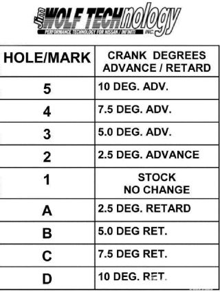
09 With the cams installed, we moved onto installing the JWT adjustable cam sprockets. Here, the newly installed cam sprocket is placed on the exhaust camshaft and indexed correctly on the timing chain by matching the mark you’ve made on the chain link that corresponds to the hole/mark one on the JWT adjustable cam sprockets. This location is the same as stock.
 |
Nissan 240SX Cam Upgrade - Build Log
|
Nissan 240SX Cam Upgrade - Build Log
10 Both cam sprockets are installed and indexed. The bolts have been torqued down to 123-130 ft-lb.
 |
Nissan 240SX Cam Upgrade - Build Log
|
Nissan 240SX Cam Upgrade - Build Log
11 With everything installed, the valve clearances must be checked. Fortunately for us, the JWT cams have been manufactured to a very accurate tolerance and the valve lash was still within spec. This saved us from having to adjust valve clearances.
 |
Nissan 240SX Cam Upgrade - Build Log
|
Nissan 240SX Cam Upgrade - Build Log
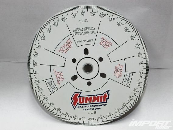
12 Having adjustable cam sprockets means we can degree them and make sure they’re timed exactly to Jim Wolf’s recommended specifications. Here is a standard degree wheel that you can purchase to do the job. This particular one is from Summit Racing and is relatively cheap. However, if money is no object, electronic ones are available as well.
 |
Nissan 240SX Cam Upgrade - Build Log
|
Nissan 240SX Cam Upgrade - Build Log
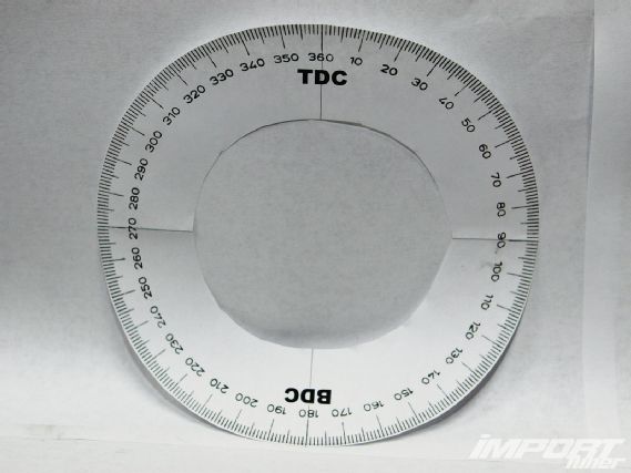
13 Unfortunately for us, there wasn’t enough room in the engine bay to install the metal Summit Racing degree wheel. We resorted to searching Google for a printable degree wheel, which we scaled to the size we needed in order to fit onto the crank pulley.
|
Nissan 240SX Cam Upgrade - Build Log
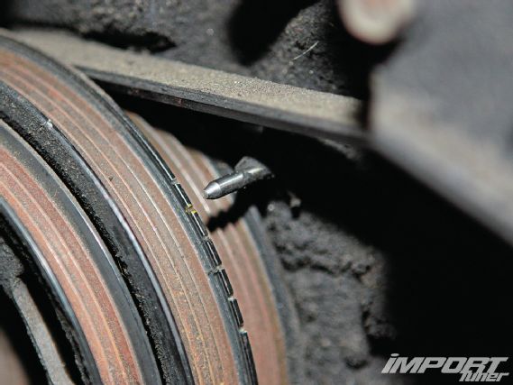
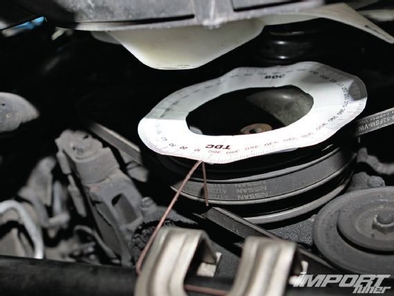
14 Here is our printed degree wheel taped to the crank pulley. It is very important to align the degree wheel as centered as possible to provide an accurate reading. After the degree wheel is placed, a pointer must be installed. In our case, we used a piece of welding wire clamped to the sway bar pointed at the TDC-0 mark.
 |
Nissan 240SX Cam Upgrade - Build Log
|
Nissan 240SX Cam Upgrade - Build Log
15 After making our adjustments, we double-checked the corrections by replotting the intake and exhaust valve opening and closing events and found that the adjustments matched JWT’s specifications.
 | Nissan 240SX Cam Upgrade - Build Log
After the installation was completed, we realized that JWT’s description of “good idle” was spot on. The motor purred as if it was stock . . . but sure didn’t feel like it!
How to Degree Cams
 | Nissan 240SX Cam Upgrade - Build Log
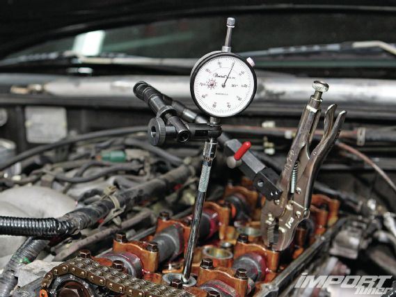
Calibrating the Degree Wheel:
We needed to verify exactly where TDC was so we used a dial indicator to accomplish this. First, remove the spark plug from cylinder number one. Attach the dial indicator to the engine and place the end of the dial indicator onto a ¼-inch drive extension. Place the extension inside the spark plug hole until the end rests on the piston. Spin the engine slightly clockwise until the dial indicator needle moves approximately a quarter way down (.025 inch) on the dial. Then note where the pointer is located on the degree wheel. Rotate the engine counterclockwise until the needle moves back up and then back down to .025 inch on the gauge. Note the reading on the degree wheel again. Take the two numbers that you’ve recorded on the wheel and zero should be exactly in the middle. If it isn’t, adjust the pointer accordingly.
Degreeing the Camshafts:
Note: There are other ways to degree a camshaft, such as finding the degree that the valve opens to a particular value or the degree at where the cam centerline value is. We degreed the camshafts by using the valves’ opening and closing events.
To check the valve events on the intake cam, we moved the dial indicator to the intake valve bucket for cylinder number one and recorded the valve opening and closing events on the degree wheel.
Move the dial indicator to the exhaust cam bucket and repeat the process on the exhaust cam. Spin the engine until the dial indicator needle moves, indicating that the valve is opening and note on the degree wheel where this event happened. Keep spinning it until the needle moves back and note the position on the degree wheel again.
After plotting the intake and exhaust valve opening and closing events, we found that the intake cam was retarded approximately 5 degrees and the exhaust cam approximately 8 degrees. We corrected this by placing the intake cam sprocket into hole/mark three, which advanced the intake cam 5 degrees. We then adjusted the exhaust cam sprocket by placing it in hole/mark four, which advanced the exhaust cam 7.5 degrees.