 | Nope, that’s not Mike. Hold your fan mail.
You are probably reading Project Car magazine because you like working on cars. Let’s go one step further and say that some of you are just getting into this crazy world of ours and are reading because you are looking for creative ideas and guidance. You might peruse our pages to learn about how to do things. To sum it up, you probably want a more complete level of knowledge, an understanding of how things work. Knowing how things work not only helps you make your car run better, last longer and go faster, it can also help you make better and more informed decisions on how to pick parts and choose directions for your own ride on the path to more performance.
In the coming months we will explain all of the basics, break it down and get to the specifics of how to extract more power from the chunk of metal connected to the wheels, known as the engine. We will explain how performance parts work, how to understand their specifications and how to pick the right parts to best fit your needs.
To understand how power parts work, you first need to understand how an engine works! Let’s get down to business and see what makes an engine tick.
Most cars are powered by what is called a 4-stroke engine. A 4-stroke is called that because there are basically 4 strokes to the power cycle, the intake stroke, the compression stroke, the power stroke and the exhaust stroke (we’ll explain those in a minute). The 4-stroke cycle is how gasoline is burned and transferred into power to the wheels.
An engine also has some major parts: the block, the crank, the rods, the pistons, the head, the valves, the cams, the intake and exhaust systems and the ignition system. These parts work in close harmony in an exacting manner to harness the chemical energy of burning gasoline. Let’s start by explaining each of these parts. For those of you who have more experience, don’t be offended. We aren’t about insulting your intelligence, but we want to get everyone on the same page!
The Block
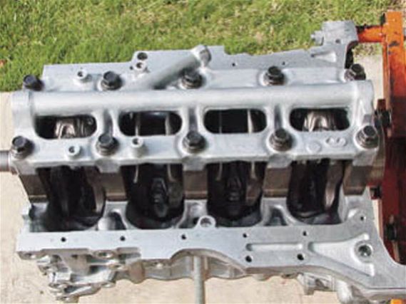 | This assembled Honda D16 block is viewed from the bottom with the oil pan off; you can see the crankshaft with the connecting rods in place.
The block is the main part of the engine that contains the reciprocating components that harness the power of gasoline. The block has bores, cylindrical holes that the pistons slide up and down in. The number of bores equates to the number of cylinders. A 4-cylinder will have 4 bores and 4 pistons, a 6-cylinder will have 6 bores and 6 pistons, an 8-cylinder will have 8 bores and 8 pistons and so on. The block also contains passages for cooling water and lubricating oil. Blocks are typically made of cast iron, but many sport compacts have lightweight aluminum blocks. Most popular sport compacts are powered by 4-cylinder engines, although some sport 6-cylinder powerplants.
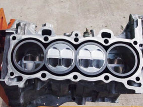 |
A top view of the same Honda D16 block. Normally, the cylinder head covers this. You can see the piston tops. Note the high dome which gives this engine a high compression ratio. This is good for all motor power.
|
A top view of the same Honda D16 block. Normally, the cylinder head covers this. You can see the piston tops. Note the high dome which gives this engine a high compression ratio. This is good for all motor power.
The Pistons
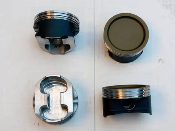 | These are forged racing pistons from a Nissan QR25DE, found in the Spec-V. The dish in these pistons lowers the compression ratio—good for turbo motors.
Pistons are aluminum cylinders that slide up and down in the bores of the block, with the top of the bores being closed off by the cylinder head. To make driving power, a flammable charge of compressed gasoline and air contained within the bore is ignited, and the piston is forced down the length of the bore toward the open end of the cylinder, away from the cylinder head with great pressure. This explosive burning of gasoline is the basic premise of how an engine works. The piston has rings that are thin, circular, springy metal seals that fit in grooves around the top of the piston. The rings’ job is to help seal combustion pressure from blowing past the piston, losing much of the power-producing pressure. The rings also help scrape lubricating oil off the cylinder, or the bores’ walls so it does not get burned up in the cylinder. If an engine had no rings, it would not be able to develop enough compression to run, as well as burn up all of its lubricating oil in just a few minutes of running.
Connecting Rods
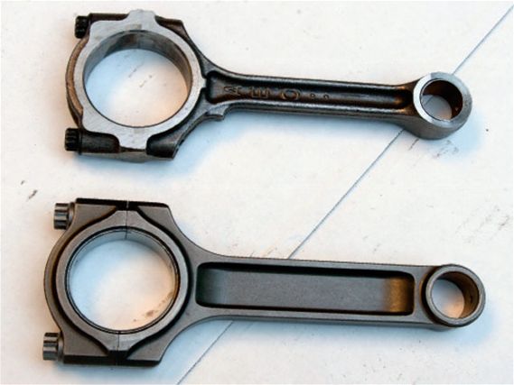 | These are connecting rods from a Nissan QR25DE. The wimpy-looking top rod is stock; the stronger-looking lower rod is made by Crower.
The pistons are attached to a dog-bone-looking metal rod. This is called the connecting rod. The connecting rod’s job is to transfer the force of the explosion by shoving the piston down the bore of the block to the rotating crankshaft. The connecting rod is attached to the piston by a pin known as the wrist pin. This is called the small end of the rod. The other end of the rod is attached to the crankshaft. This is called the big end of the rod because the crank’s journals are much bigger than the wrist pin journals. The crank journals are bigger because the crank continually rotates at a high speed as opposed to the simple rocking movement at the wrist pin end of the rod. The high-speed rotation requires additional bearing area to prevent the rod and crank from being damaged by friction. The big end of the rod spins smoothly on the journal of the crank on a pressurized oil film sleeve bearing. On a typical sport compact motor, the small end of the rod has a bronze bushing for the wrist pin.
Crankshaft
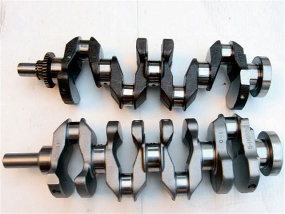 | Two different crankshafts from a Nissan QR25DE. The lower part is fully counterweighted, better if you want to build a high-rpm engine.
The crankshaft, or crank for short, is exactly like the crank on a bicycle. It transfers an up-and-down force into a rotating motion that can be used to spin the wheels. The crank has offset throws, exactly like your bicycle crank, but it’s driven by the rods and pistons instead of your legs. More precisely, the explosion of ignited fuel and air occurring in each cylinder forces the pistons down the bore to rotate the crank. This is what makes your car go! After the piston goes down, the crank rotates and the piston is pushed up the bore again until it reaches the top, where it can be pushed down again by another explosion of fuel and air. The crank rotates on its main journals on an oil film sleeve bearing just like on the big end of the rods.
The Cylinder Head
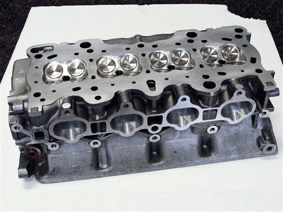 | This Toyota 4AG head is fully ported and polished by Dan Paramore Racing. The 4AG is found in the AE86 Corolla.
The cylinder head is, on most sport compacts, an aluminum casting that caps off the top of the block and contains the spark plugs, camshafts, valves and the valvetrain. The head must contain the explosive force of the igniting fuel/air mixture so the explosion of said mixture can only drive the piston down the bore instead of blowing out of the bore’s top. The cylinder head has the combustion chambers cast into it. This is the area where the valves and spark plugs are located. When looking at the underside of the cylinder head, the side that bolts to the block, the combustion chambers are the depressions that line up with the bores. It is in these chambers where, when the piston is at the top of its stroke, the fuel/air mixture is ignited, kicking off the power stroke. The cylinder head also has cooling jackets filled with circulated water to help keep the combustion chambers from getting too hot. The valve cover is simply a cover that protects the valves, cams and springs on top of the head. The head gasket is a layer of softer material sandwiched between the head and the block, and it helps seal the two surfaces from combustion pressure.
The Valves
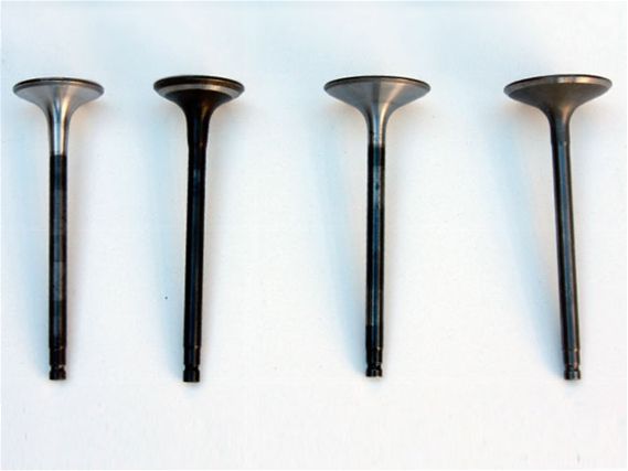 | These Nissan intake valves are found in the QR25DE engine. The shiny ones have been reshaped for better flow.
The head contains the intake and exhaust valves. The intake and exhaust valves are spring-loaded, poppet-type valves. The springs hold the valves shut but allow them to be opened with a push. The intake valves open to admit the explosive mixture of fuel and air into the combustion chamber. They then close to allow the engine to build up compression as the piston, driven by the crank, comes up to TDC or top dead center—this is what engine-builders call the event when the piston is at the top of the stroke. When the spark plug ignites the fuel/air mixture, the piston is driven down and the exhaust valves open near the bottom of the piston’s downward travel, allowing the burnt waste gases to escape to prepare the combustion chambers for the next charge of fresh fuel and air.
The Camshaft
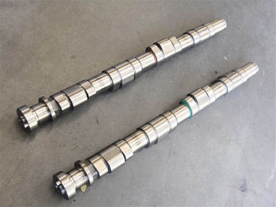 | These cams are from a Nissan SR20VE. Looking at all the lobes gives you an idea why old-timers call these bumpsticks.
The valves are opened and closed by the camshaft or camshafts, which are basically rods with off-center bumps or lobes that spin in the cylinder head at half of the crankshaft’s speed. The lobes of the camshaft push the valves open and closed so that air and fuel can be admitted and burnt exhaust expelled. Sometimes the cam works directly on the valve. Many motorcycles and racing-type engines are like this. Typically, the camshaft works the valves through a rocker arm which is like a miniature teeter-totter. One end of the rocker arm rubs on the rotating camshaft with the other end pushing the valves open and closed.
Sport compact engines are typically called overhead cam engines. This means that the camshaft is contained within the cylinder head on top of the valves. This is opposed to overhead valve engines like low-revving, old-school domestic V-8s that have the camshaft located in the middle of the block, connecting to the valves with, lifters, long pushrods and rocker arms. Overhead cam engines are better for the typical high-rpm, small-displacement sport compact motor, because they have simpler, lighter, more direct acting valvetrains. These valvetrains work better at high rpm because their lower inertial mass allows them to follow the camshaft’s lobes with more accuracy. If the engine has only one camshaft that controls both the intake and exhaust valves, it is called a SOHC or single overhead cam motor. The Honda D16 that was found in the ever popular Civic and the Nissan VG30 found in older Nissan trucks and pre-’89 300ZXs are examples of SOHC motors.
Many sport compact motors have dual overhead cams, which means that there are separate cams for the intake and the exhaust valves. The advantage with this is that the cam can be placed very close to the valve, allowing the cam’s lobes to either work directly on the valves or through a very small rocker arm. This reduces the inertial mass of the valvetrain to a minimum, which helps high-rpm operation even more. Just about all of the higher-performance sport compact motors use dual overhead cam valvetrains, also known as the DOHC configuration. The Nissan VQ35DE, the Mitsubishi 4G63 and the Honda K20A are prime examples of DOHC motors.
The Intake System
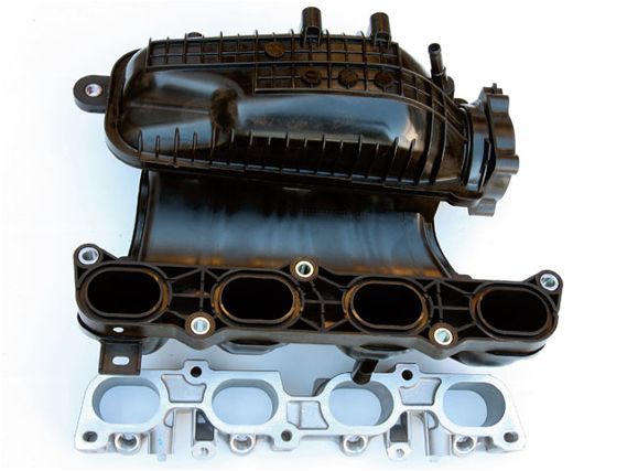 | The intake manifold brings air from the throttle-body to the intake ports in the cylinder head.
The intake system consists of the manifold, which is basically a series of pipes that connect the throttle-body, which is the valve that controls the amount of air that can reach the insides of the motor to the cylinder head’s intake ports. The throttle controls the amount of air the engine can suck in, thus controlling its speed and power. When the throttle is shut, the airflow is very limited, so the engine must idle. When it is wide open, the engine takes in all the air it can to produce its maximum power level. The manifold usually contains the fuel injectors, which are electro-mechanical valves controlled by the ECU (or engine control unit), a small computer that is the engine’s brain. The ECU controls the amount of fuel being injected into the engine by modulating the open and closed time of the injectors. When the throttle is fully opened, allowing the maximum amount of air possible into the engine, the ECU will command the injectors to stay open longer so they can inject a proportionally greater amount of fuel to create a bigger volume of explosive fuel/air mixture. More fuel/air mixture means a bigger explosion and more power.
The Ignition System
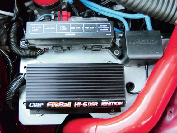 | This Crane Hi-6 ignition is very powerful and is good for turbo and nitrous applications that need a hot spark.
To get the fuel/air mixture burning, the ignition system ignites the flammable mixture by firing a powerful electrical spark across the electrodes of the spark plug. The engine’s ECU controls the timing of this spark. The spark is fired as the piston has almost risen to Top Dead Center (TDC) near the peak of the cylinder’s highest compression. This is the most efficient time to fire the spark. Usually, the timing of the spark advances as the engine’s rpm increases. This is because at higher rpm there is less time for the combustion event to take place, so it must be started sooner in the cycle to maintain proper operation.
The Exhaust System
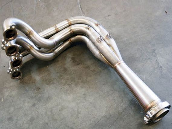 | A tubular manifold that is designed to flow well is called a header. This header is made by Burns Stainless and can give more than 50 hp on a highly modified motor over the stock exhaust manifold.
The exhaust system is simply the tubing that directs burned exhaust gases away from the motor. The exhaust system consists of the exhaust manifold, the catalytic converter and the exhaust pipe. The manifold collects the exhaust gas from each individual exhaust port in the cylinder head and collects them into a single pipe. This pipe leads into the catalytic converter where poisonous constituents of the exhaust gas, such as nitrogen oxide (NOX), various unburned hydrocarbons (HC) and carbon monoxide are converted to non-toxic CO2 and water vapor. After the catalytic converter, the gases flow into the exhaust pipe where they pass through the muffler, which reduces the noise to an acceptable level and out into the atmosphere.
The Cooling System
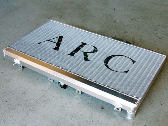 | This aluminum ARC radiator cools twice as well as a stock part. Great for hot summer track days.
The cooling system circulates a mixture of antifreeze and water throughout the block and head, keeping them from getting too hot from the continuous explosions that they are subjected to internally. The water is pumped by a vane-type pump driven off of the crank by a belt, out of the block to the radiator (located in the very front of the car), where it is cooled down by the airflow around the moving car and recirculated back through the engine.
The Lubrication System
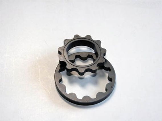 | This is an oil pump gear from a Nissan SR20 engine.
The lubrication system keeps things spinning smoothly with little wear. Oil is sucked up from the oil pan by a gear-type pump driven from the crank, usually by a chain and fed through the oil filter to help keep it clean. The pressurized oil is then fed to the engine’s main and rod bearings. Oil is also fed to the camshafts. Oil escapes from the cam journals, rod and main bearings and is splashed around inside the block and under the valve cover. This splash keeps a lot of stuff lubricated. The pistons and rod wrist pins usually rely on oil scraped off the cylinder walls by the rings and this splash. The cam lobes and rocker arms are partially lubricated by this splash as well. The oil splash settles and drains to the bottom of the engine, where it collects in the oil pan. The oil pump picks it up and sends it on its way around the engine again.
Now that you know what all of the basic parts of an engine are and what they do, it’s time to understand how they work together as a system. Four-stroke engines use what is called by engineers the Otto Cycle or the 4-stroke cycle to turn gasoline into power. Tuning the 4-stroke cycle is how more power from a motor is obtained, so it is important to know what the different parts of the cycle are and how they affect your power output.
The Intake Stroke
Let’s start with the piston at TDC. The intake valve is starting to be opened by the camshaft as the exhaust valve is closing. As the crankshaft turns, the connecting rod starts to pull the piston down away from TDC. The turning crank is also linked to the camshaft by a chain or belt so as the crank turns, the intake valve is opened more and more until it is fully open. The downward-traveling piston creates suction in the cylinder so air and injected gasoline from the intake manifold are drawn into the cylinder. This continues until the piston is all the way to the bottom of the crank’s stroke or BDC, also known as Bottom Dead Center. Because of the cam’s shape, the intake valve is almost totally closed by the time the piston is at BDC. At the end of the intake stroke, we are left with a cylinder full of fresh fuel/air mixture.
The Compression Stroke
Now the piston starts its trip upward after being pushed up by the crankshaft and the connecting rod. The intake and exhaust valves are fully closed and as the piston is forced upward, the fuel/air mix is compressed. This compression forces the fuel and air molecules closer and closer together until they become a highly reactive/explosive mixture; the closer the proximity of the molecules, the easier it is to initiate an explosion. When the piston nears TDC again the ignition system fires the spark plug and triggers an explosion in the cylinder.
The Power Stroke
By the time the piston is at TDC, the explosion of fuel and air in the tightly contained cylinder is well underway. The heat and pressure of the explosion rise rapidly and the piston is pushed back down the cylinder with great force. This is the driving power that spins your wheels and propels you down the track. As the piston is pushed down the bore, the cylinder pressure starts to decrease as the cylinder’s volume increases. As the piston nears the bottom of the bore, the camshaft starts to open the exhaust valve.
 | A cutaway Honda H22A engine from JUN Auto shows how the block, crank, rods, piston, head, valves and cams all relate to each other.
The Exhaust Stroke
Nothing too exciting goes on during the exhaust stroke. As the piston once again starts to go up from BDC, the exhaust valve opens and the burnt exhaust gas is forced out of the cylinder by the rising piston into the exhaust manifold—through the catalytic converter, down the exhaust pipe, through the muffler and out. By the time the piston is back at TDC, the exhaust valve is almost closed and the intake valve is starting to open. The cycle is about to start again. The part of the cycle where both the intake and exhaust valves are open is called overlap. Overlap helps the incoming fresh fuel/air mixture force the remnants of the stale burnt exhaust gas out of the combustion chamber.
A 4-stroke engine has one power stroke in each cylinder for every two revolutions of the crank. Since a camshaft has one bump on each lobe, it is driven at half the engine speed, so the cam will open the valve at every other revolution of the crank as necessary. Imagine this stuff happening at 7000 rpm! The cycle would be repeating itself at about a rate of 60 times a second in each cylinder. At that speed it is easy to imagine a more uninterrupted flow of power coming from this seemingly herky-jerky system.
Modifications
Manipulating the timing and amounts associated with these events to increase power is what tuning is all about. We will get more into the specifics of this in later issues of Project Car. Now that you understand the fundamentals of how an engine works, explaining how to make it more powerful is the easy part!
Stay tuned to this channel for more!