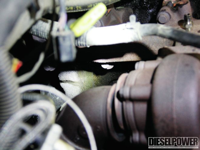
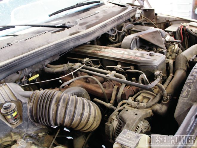
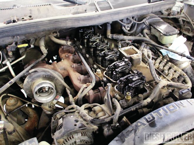
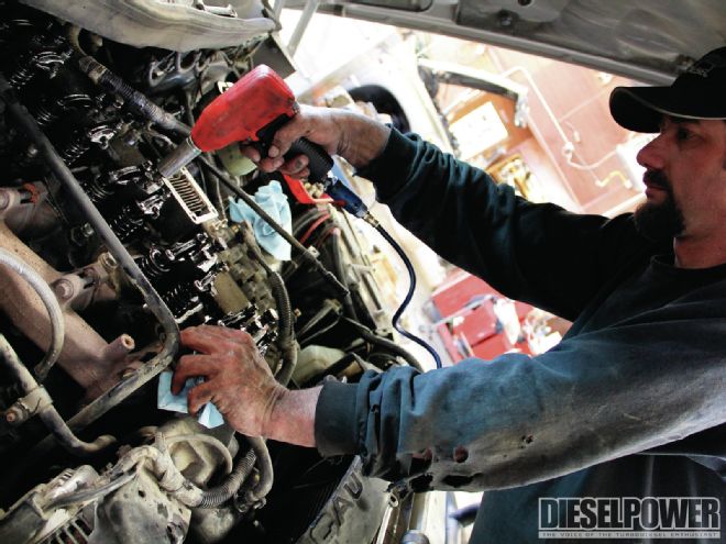
We were rolling along smoothly with Project Triple Threat, our ’95 Dodge 2500 4x4, until we noticed a little issue. The engine was leaking water. At a paltry 100 hp more than stock, our factory head gasket decided to give up and started to leak water onto the side of the block. At first it was just a couple of small streams, but by the time we addressed it (a few months later), it had become a 4-inch-wide waterfall.

| gateway To Power removing The Manifold
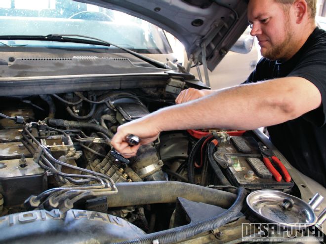
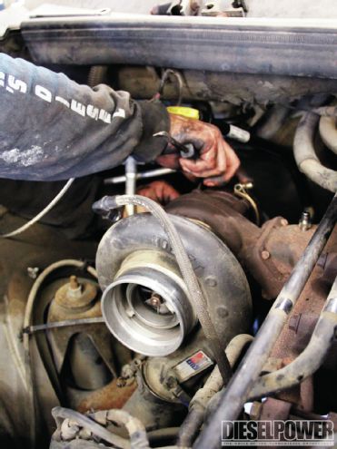
We could keep upping the power of our Cummins engine, but the water leak would only get worse over time. So we took care of the problem sooner rather than later and replaced the head gasket and installed a set of ARP 2000 studs to ensure we wouldn’t have any head sealing issues in the near future (up to about 600 to 700 hp). With the help of Brown’s Diesel in Riverdale, California, we tackled the task in about a day.

| gateway To Power torque Sequnce
Specialty Tools
There are a few specialty tools that are needed for this job—mainly an engine hoist, an injector puller, and a torque wrench. There are some other tools, which, while not necessary, are very helpful for the job as well. These tools are: a barring tool (to turn the engine over when setting valve lash) and a professional-grade straightedge (to check the straightness of the deck of the engine block). If you don’t have an engine hoist, that’s something that can usually be rented or borrowed. There’s a neat and cheap ($20) injector puller you can get from www.torkteknology.com. And the barring tool is something to purchase from your local specialty tool guy, or even Summit Racing. A straightedge can be found (or borrowed) at most places that sell high-end tools, and if you don’t own a quality torque wrench, now might be a good time to buy one.
How to Adjust your Valve Lash
One task that puzzles some enthusiasts after they replace a head gasket is how to check their valve lash. To do so, the intake valves must be set at 0.010 inch, while exhaust valves come in at 0.020 inch. The process of setting an engine’s valve lash begins by tightening the rocker arms (loosely) to zero lash. Then, rotate the engine over using either a barring tool or—if your belt and tensioner is in good shape—the alternator pulley. When the back cylinder (number 6) is at overlap (the rockers will be crossing each other in opposite directions), stop turning the engine. The number 1 cylinder should now be close to top dead center (TDC), which means both the intake and exhaust valve can be adjusted. At this point, the intake valves for the number 2 and number 4 cylinders can be adjusted, as well as the exhaust side rockers for number 3 and number 5. After this is accomplished, turn the engine 360 degrees. The rockers on the number 1 cylinder should now be crossing, which means number 6 is close to TDC. At this point, the intake and exhaust rockers for number 6 can be adjusted, as well as the number 3 and number 5 intakes, and number 2 and number 4 rockers on the exhaust side. Keep in mind, the adjusting nuts only need to be torqued down to 18 ft-lb, so don’t go crazy on them when setting lash.

| After the rocker pedestals were installed and the head studs were tightened down, the valves were adjusted. Check out the third sidebar for this procedure.
