| 2001 To 2004 Chevy Lb7 Duramax turbo Diesel
In 1997, Isuzu Motors Ltd. and General Motors created DMAX Ltd., a joint venture for producing diesel engines. The Duramax 6600 was the first engine that came into fruition after this relationship started.
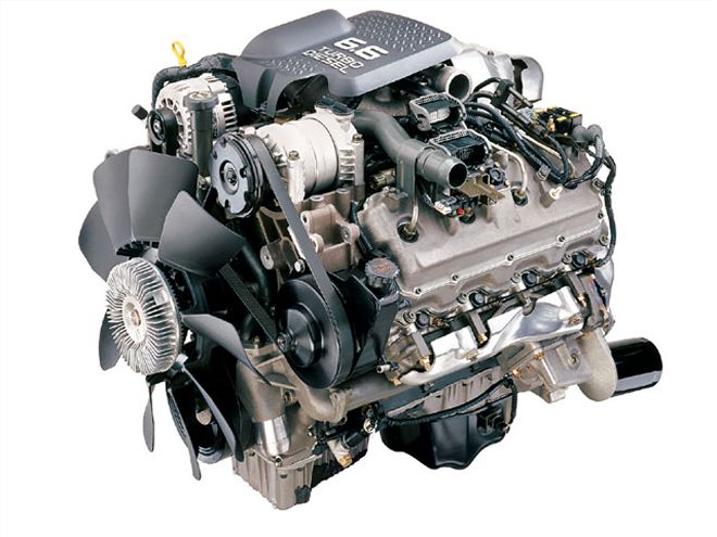
The LB7 Duramax diesel is a direct-injected, turbocharged, intercooled, four-valve-per-cylinder V-8 that produces 300 hp and 560 lb-ft of torque. Starting from a blank sheet of paper, the 6.6L Duramax is recognized to date as the fastest diesel development program in the world.
It went from concept to initial production in only 37 months. This included the construction of a brand-new "green field" manufacturing plant in Moraine, Ohio. The 600,000 square-foot facility resides on 40 acres and includes four machining lines, a heat-treat facility, and engine assembly. In addition, machining of the cylinder blocks, cylinder heads, crankshafts, and connecting rods are accomplished in Moraine. The factory currently has capacity to produce 105,000 engines per year.
Duramax production of the LB7 engine began in the summer of 2000, and the project was a collaboration of engineering talent from GM and Isuzu-each taking the lead in their respective area of expertise.
Size MattersGasoline engines had dominated the fullsize pickup class, so General Motors' goal was to design a diesel engine that would take up no more space than the gasoline engine it would replace as an option. Because a diesel requires additional equipment-such as a turbocharger, injection pump, and intercooler-this needed to be acknowledged during the early stages of development. Due to this requirement, the architecture of the engine would include the following: the turbocharger, fuel-injection pump, and fuel rails that would be installed in the valley of the engine block for a smaller engine profile. The oil cooler was directly attached to the left side of the cylinder block. Coolant would be distributed to the left and right banks through a water passage in the flywheel housing. This simplified the coolant piping and would also increase reliability by facilitating even temperatures for both sides of the engine.
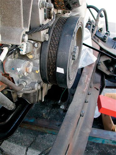
Auxiliary equipment-such as the air conditioner compressor, the power-steering pump, and the alternator-would be driven by one serpentine belt. The mounting brackets for the accessories would be located on the front surface of the engine for ease of in-field service and assembly plant installation
Engine BlockThe rigidity of the cylinder block was a concern not only for durability but for noise suppression as well. This was accomplished with a deep-skirt cylinder block structure and by connecting the bearing caps to the lower part of the block with side bolts, in addition to the two main bolts. The Duramax block is manufactured from a special gray iron alloy.
The upper portion of the block is a closed-type and has a structure designed for minimal deformation at the high combustion pressure of a diesel engine. Another goal was to decrease the lower portion of the engine's width.
Minimizing bore distortion was important for maintaining the piston rings' sealing performance and to ward off engine seizure. This was done by evenly positioning six cylinder-head bolts around each bore by evenly distributing coolant around each independent cylinder and arranging cooling water holes on the cylinder-head deck surface. The six head bolts around each cylinder also help the gasket withstand the high in-cylinder pressure of a direct-injection, turbocharged engine. The upper portion of the linerless cylinder bore is induction hardened to reduce wear.
Cylinder HeadsThe cylinder head is made of gravity-cast aluminum and has a four-valve design for good volumetric efficiency and blowdown during the exhaust cycle. The fuel injector is located in the center of the combustion chamber along the cylinder line. A stainless sleeve is pressed into the cylinder head, and the fuel injector is inserted in it. The arrangement of the valves is categorized as a "twist type." This describes the two independent intake ports that are designed to maximize tangential flow for optimum intake swirl.
Adequate and even cooling of the valve seats greatly contributes to minimizing any change in the valve lash. There is a large space between the valve seats that uses the cooling ability of aluminum to reduce the heat deformation. An aluminum cylinder head has higher heat conductivity, so it has a lower temperature on the surface of the combustion chamber when compared to a cast-iron design. With a cast-iron test cylinder head, the exhaust valve seat temperature was 608-662 degrees Fahrenheit. With the aluminum cylinder head, which also benefited from a larger space between the valves, the temperature was maintained at 428 degrees or less. The lower temperature enhances durability of the valve seats and increases reliability of the engine as a whole
Head GasketsThe head gasket has a steel laminate structure composed of three stainless steel plates (each plate is fluorine coated). Steel laminate deteriorates very little over time and is highly heat resistant, so it can withstand high in-cylinder pressure.
Head BoltsSix 14mm head bolts are used per cylinder. These provide adequate surface pressure for both the bore seal and coolant seal portions. The optimum torque for the bolts was determined by extensive testing.
The head bolts are a torque-to-yield design that cannot be reused once removed from the engine. This technology places the bolt in what is referred to as the plastic range. The theory has the bolt tightened to a desired specification and then with a torque angle gauge installed, turned a prescribed number of degrees. This eliminates the large variation of axial force that occurs with a traditional torque-to-specification head bolt and will guarantee good sealing and little possibility of in-field service issues.
CrankshaftTo cope with the high cylinder pressure of a 300hp diesel engine, the pin and journal diameters of the crankshaft are 2.48 and 3.15 inches, respectively-the 4340 steel forging using a 90-degree plane twist method. The entire crankshaft is also treated to the Tuftriding process for additional strength.
An eight-mass counterweight method was chosen, and a balance weight is added to the crank pulley and the flywheel in order to keep the crankshaft as compact as possible. There is an oil passage from each journal to the connecting rod pin, which lubricates the connecting rod bearing for each cylinder. The journal bearing is a Kelmet design with an overlay. The total thickness, including the steel backing, is 0.98 inch.
Camshaft DriveTwo gears, one for driving the camshaft and another for driving the oil pump, are attached to the front end of the crankshaft. The gear used for driving the oil pump has a 57-tooth disc attached, which is used to generate a pulse for the crankshaft sensor. The flywheel is attached using eight 16mm bolts on a 3.23-inch circle diameter. An axial seal is used for the oil seal at the front and rear of the crankshaft in order to resist deterioration over time.
| 2001 To 2004 Chevy Lb7 Duramax pistons
PistonsThe pistons are made of high-silicon aluminum alloy made through a gravity-casting process. To reduce noise, a cast-in strut is employed. The three piston rings consist of two compression rings and one oil control ring. The top ring is a barrel design. A Physical Vapor Deposit (PVD) is used to put a negative ion plating on the surface of the top ring. This coating provides excellent durability. The second ring is undercut and the oil ring has a backup spring. A ring carrier is cast into the top ring groove, to minimize any wear of the ring grooves. To accept the high thermal load, an oil cooling spray wets the underside of the piston.
Connecting RodsThe piston pin diameter is 1.36 inches, and the connecting rod is made of forged steel. A fractured cap (or cracked cap) division method is used on the larger end of the connecting rod to improve precision in fastening the two parts together. Because this is a structure in which the cap portion is rejoined exactly with the upper section, the shape of the bearing housing has improved accuracy.
ValvetrainThe overhead valve mechanism minimizes friction and wear by using a pair of rocker arms for each set of intake and exhaust valves. Each forged steel rocker arm uses a bridge to operate two valves. The bridge does not have a guide because this component complicates adjustment of the valve lash.
The portion of the rocker arm that touches the bridge has a sintered iron tip, and the bridge has a hardened steel cap at the contact point. This combination has good wear resistance to minimize any changes in valve adjustment.
CamshaftThe steel roller camshaft's surface is induction-hardened and the forged roller tappet is carburized. The pushrod is made of steel tube. Because both ends of a pushrod have a tendency to wear, extra material was added to those areas. Also, lubricating oil is forced through the hollow shaft of the pushrod to help minimize the lash change over time.
Cooling SystemThe cooling system routes coolant to the back of the engine first and then around the cylinders toward the front of the engine. The coolant goes through a passage in the flywheel housing in the rear of the engine toward the left and right sides of the cylinder block. After coolant flows forward around the cylinders and up to the cylinder heads, it then goes through a tube at the front of each head and to the thermostat housing. Dual thermostats are employed, with opening temperatures of 180 and 185 degrees. The coolant also travels from the water pump to the oil cooler, which is attached to the left side of the cylinder block. This increases the accuracy of temperature control in the engine.
Injection SystemThe design team decided on a Bosch common rail system that consists of a high-pressure supply (CP3) pump, a function block, and a common rail with a fuel injector for each cylinder. The pump is driven at crankshaft speed. The injection pump has a gear-type feed and a rail pressure control valve. An advantage of this design is that injection pressure can be raised independently of engine speed.
This means the size of the nozzle hole in the injector can be reduced, which, in conjunction with the high operating pressure, makes for better atomization and faster combustion. Pilot injection is used to limit tailpipe emissions and reduce combustion noise.


