| international 420ci Diesel Engine engine Block
In March of 1978, the International Harvester Corporation started development of an engine that would eventually change the way pickup trucks and light-duty vehicles would be powered. The 420ci (6.9L), naturally aspirated (non-turbo), indirect-injected (IDI), diesel V-8 would find a home under the hood of Ford pickup trucks, and the diesel power culture would be born.
The Ford/IHC 6.9L engine featured a bore of 4.00 inches, a stroke of 4.18 inches, produced 170 hp and 310 lb-ft of torque with a 20.7:1 compression ratio. It may not sound like much by today's diesel standards, but 24 years ago it started a diesel revolution!
Engine BlockMade from cast iron, the 6.9L featured 4-bolt, nodular iron main bearing caps. This was done for reliability and also to increase the stiffness of the lower end of the block. In addition, typical of light-duty engines, bulkhead window core support holes were eliminated. This further increased stiffness and eliminated a potential area of failure.
IHC engineers used the then-new finite element analysis procedure to optimize performance. This study indicated that a significant reduction in deflection could be realized by increasing the bulkhead thickness in the area around the cam bore from 0.62 inch to 1.12 inches. This change was incorporated into the production engine.
The cylinder bores were not siamesed and were 0.26-inch thick. The five head bolt bosses per cylinder were not joined to the cylinder walls, but tied directly to the main bearing bulkheads through the outer water jacket walls or free-standing interior bosses. The design was used to minimize cylinder bore distortion during machining, assembly, and in operation. The front end of the engine block was extended to form a cavity for the geartrain and provided an ideal location for the fuel lift pump, thermostat, thermostat bypass, and water cross-over between the cylinder heads.
The 6.9L block also included many advantages in terms of flexible packaging for use in varied vehicles and to improve in-field service. The pan rail had tapped holes for oil pan mounting and were arranged for a reversible oil pan along with either a front or rear dipstick. The water inlet cavity provided flexibility for both size and location. Light-duty truck mid-engine mounting bosses and heavy-duty truck front-mounting bosses were included in the design. The engine block valley was cast open, and the roller valve tappets were serviceable without removing the cylinder heads.
A positive-displacement geardriven oil pump was located at the front of the first bearing cap and driven by the crankshaft gear. The pump was mounted to, and located by, the same machined surfaces as the bearing caps; doweled location holes were not required. Oil was routed via drilled passages throughout the crankcase. No external lubrication plumbing was required.
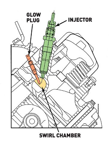
| The injectors were placed inboard along with the glow plugs.
Rotating AssemblyThe crankshaft was designed to the same criteria that IHC applied to its heavy-duty line of diesel engines. For reliability, a forged steel material was chosen, which could be sufficiently strengthened. Through extensive testing, the operating stress levels were measured in the critical areas. From those measurements, the manufacturing process and heat-treatment requirements were established.
The crankshaft was forged from 15B28H steel and quench-and-tempered to a minimum hardness of 217 Brinell hardness number (BHN). The five main and four pin journal surfaces were induction-hardened to Rockwell hardness (RC) 50-55 for wear resistance and to allow in-service re-grinding. The pin fillets were induction-hardened to Rockwell hardness 50-55, then ground flush with the pin surface for fatigue life. The combination of processes and design provided a very strong crankshaft and a long service life.
External balance weights in the flywheel and a vibration dampener were required to keep the overall engine size within that of a gasoline engine and to limit the scrap rate during manufacturing.
The front and rear crankshaft oil seals were a one-piece design that were springloaded and featured trimmed flouroelastomer material. Both oil seals rode directly on the ground sealing surfaces-the front seal on the vibration dampener and the rear on the crankshaft rear flange.
The connecting rod and cap were forged from alloy steel as one part and cut into two pieces early in the machining process. In order to achieve adequate fatigue strength, the forging was heat-treated to obtain a surface hardness of Rc 27-33. This also provided adequate core hardness for surface strength of the critical stress areas. After heat treatment, the rough forging was shot-peened to provide a margin against flaws as well as undesirable residual stresses from operations such as straightening.
The small end of the rod used a steel-backed bronze bushing, which was pressed in place and bored to the final dimension. As was traditional IHC protocol, the rod design was proved acceptable by both static strain and fatigue tests prior to running in an engine.
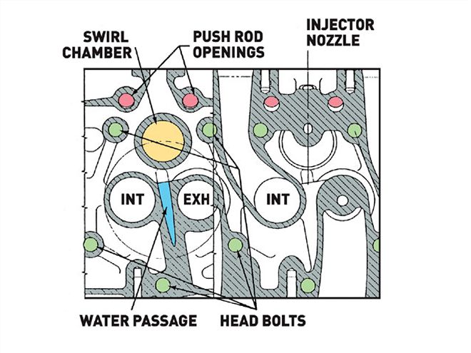
| The cylinder head cross-section shows the pre-chamber along with the placement of the nozzles and pushrods.
Pistons and RingsThe piston design focused on the durability that was an IHC hallmark. Although analysis had shown the mechanical strength would be sufficient, the required three compact ring package and short top land could result in high ring groove temperatures and a potential for ring sticking, poor oil control, and scuffing. However, a longer piston would have required increasing the block deck height with the resulting increase in engine dimensions. Finite element analysis was employed to predict the mechanical/thermal stress conditions and ring groove distortion related to the thermal concerns. The intention was to depend on oil cooling of the piston for temperature control, and the compact design was determined to be adequate, as initially proposed. An Alfin-bonded nickel-plated insert was used to control top-ring groove wear.
The piston pin was an extruded design made of a medium carbon steel that was carburized to control strength and wear properties. Its 1.11-inch outside diameter and 0.58-inch inside diameter, resulting from the extrusion process, provided strength and deflection control.
In order to provide adequate piston lands, relatively narrow rings were used compared to previous IHC diesel engines. Both compression rings were 0.08-inch wide. The top ring was a ductile iron, chrome barrel-faced design, while the second ring was a gray iron, positive twist, taper-face style. The oil ring was 0.109-inch wide and was made of ductile iron and spring loaded.
Cylinder Heads and Combustion ChambersA Ricardo Comet V combustion system was selected during the early stages of development for the 6.9L engine. It was chosen because of its modern design that would meet the stringent emissions requirements expected in the 1980s. The design would also provide a high power output and good fuel consumption at a relatively low cost.
The cast-iron cylinder head was a two-valve design with the combustion chamber placed in the piston crown. To reduce the valve bridge operating temperature, a drilled cooling jet was utilized. The cooling passage provided more uniform temperatures in the valve seats and eliminated the potential for valve bridge cracking during high-load uses.
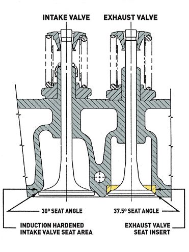
| The intake valve used an induction-hardened seat, while the exhaust side employed a hardened insert.
Originally, an exhaust seat insert was an anticipated requirement with the heat load of an IDI engine. The inserts provide superior wear resistance and improve serviceability over non-inserted, induction-hardened seats. Early testing by IHC had shown adequate wear resistance. However, as testing continued, a problem of head cracking was encountered. Several modifications proved fruitless, so the exhaust insert design was reincorporated. The cracking problem was not encountered on the intake seats, which employed only an induction-hardened seat.
The head gasket design featured a solid steel core carrier that was 50 percent of the total gasket thickness. The rest of the gasket consisted of a rubber-abestos material. Combustion sealing was done with a free-floating solid carbon steel wire wrapped with a stainless steel armor. The armor was shaped with a "bib" under the swirl chamber insert to protect the underlying facing material.
| The fuel system used a very straightforward and reliable Stanadyne rotary distributor injection pump.
IDI Fuel SystemIHC used a Stanadyne DB2 rotary distributor fuel injection pump that incorporated a hydraulic speed advance and a light load advance for optimum timing over the entire operating range.
Additional advance was achieved during cold starting and warm-up to reduce white smoke and hydrocarbon emissions. A solenoid controlled by a thermo-switch in the cooling system unseated the ball valve of the housing pressure regulator. This reduced housing pressure, which allowed a greater amount of injection advance for the given load and engine speed.
The governor was a minimum/maximum design, providing control action in the low idle speed range and above the rated speed. Between these ranges, the throttle lever controlled the metering valve position. A snubber orifice machined into the distributor rotor indexed with the ports in the head after the main injection took place. The damper orifice reduced aftershocks in the injection lines and eliminated unwanted secondary injections of fuel.
Outward opening poppet nozzles were tested first with a 30-degree angle toward the swirl chamber wall and a smaller hole spraying 10 percent of the fuel toward the glow plug. Performance with this design was satisfactory, but hydrocarbon emissions were high and coking of the small 0.009-inch orifice proved to be a problem. As a result, inward opening pintle nozzles were developed to fit in the space confines of the 0.67-inch orifice nozzles. Performance, emissions, and durability all proved to be excellent with the new design-and nozzle coking was kept at a minimum.
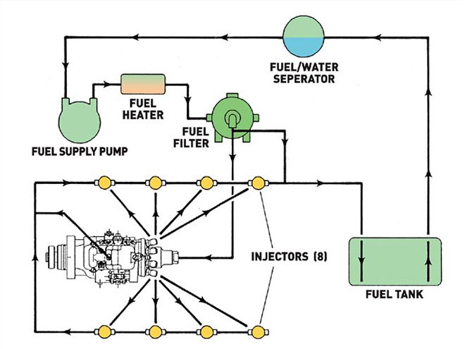
The fuel system was mounted on the engine and included a mechanical fuel lift pump, inline fuel heater, and a fuel filter prior to the injection pump. A constant bleed orifice was used on the outlet of the fuel filter to eliminate the need for hand priming or manually bleeding the air from the system when the filter was changed or the tank was allowed to run dry.
An electrically activated glow plug was used in each swirl chamber to improve starting below 70 degrees Fahrenheit. The glow plug temperature was controlled by an electromechanical bi-metallic switching device, which pulsed 12 volts to the 6-volt glow plugs. The initial energized period of up to 10 seconds pre-glow produced glow plug temperatures that provided acceptable engine starting to minus-10 degrees. The system incorporated an after-glow feature that continued to activate the glow plugs for a period of about 1 minute after the engine started. This feature reduced the amount of white smoke developed on cold start until the combustion chamber walls were sufficiently heated. For starting below minus-10 degrees, a 110-volt electrical block heater was provided.
A Successful DesignThe 6.9L engine underwent extensive development and durability testing before the start of production. A total of 160 prototype and 10 pre-production engines were built for engineering tests. The test engines had accumulated a total of 52,000 laboratory durability test hours and 815,300 miles of field tests by the time Ford vehicle production began.
The laboratory tests included:* 21,000 hours at full load
* 16,500 hours at 72 percent load
* 4,500 hours of special durability tests
* 10,000 hours on pre-production engines
The 10 pre-production engines were built and tested on the dynamometer to verify the quality of the production process. Each engine was subjected to 1,000 hours (approximately 80,000 miles) at full load, with no problems occurring. In addition, pre-production engines were placed in customer fleet trucks and subjected to varied conditions, drivers, and use.