QuestionQUESTION: Bought a john deere 68 fixer-upper, and I was told that it ran. The key switch had been "robbed" and in the process, there were some wires cut. It will run briefly when jumped directly to the battery, but thats it. I found a couple wiring harness pictures, but no schematic, so I'm guessing where everything connects. Does anyone have a good schematic, even hand drawn?
ANSWER: I looked at the parts list at jdonline, and they just showed some crude drawings, but no schematic.
http://jdpc.deere.com/jdpc/servlet/com.deere.u90490.partscatalog.view.servlets.H
It shows a "keyswitch" with one wire, so that would just be a shutoff switch, does yours have a switch with an off /on/crank position? If so, how many terminals are on it?
These systems are not at all complicated, breaking the systems down.
The shut off circuit, must be kept separate from the cranking/
charging circuit, as any voltage supplied to the ignition will damage it, so the wire from the keyswitch to the ignition, just serves to "ground" out the ignition, thus shutting off the engine.
On the parts list, I see both pics of a Briggs and a Tecumseh, but this will apply to either.
Some older Kohlers had a battery type ignition, which is different.
there is a battery, starter, and a "solenoid" in between, the solenoid is a heavy duty switch that sends the high amp current
from the battery, to the starter. A keyswitch would melt.
On the one terminal on the solenoid, the one attached to the battery, there should also be a smaller wire which sends voltage to the keyswitch's B terminal., then when the key is turned to crank,
voltage is sent from the keyswitch back to a small terminal on the
bottom of the solenoid, which when voltage reaches it, the solenoid activates and cranks the engine, when the key is released, the
keyswitch goes to the run position.
That is the most basic description of the electric system, there are usually fuses, safety switches, gauges, etc., in between, more so
on the newer mowers, but keeping the path of the cranking system, and the kill circuit, in mind, you can route the wires correctly.
Unfortunately, JD does not make wiring schematics readily obtainable
Anyway, I hope this helps,
Let me know how things are coming,
Fish
---------- FOLLOW-UP ----------
 JD 68
JD 68
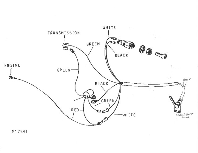
QUESTION: Fish-
See the attached image. This is what I have as far as existing wires go. The white and black wires were cut where the key switch would have been. I understand the battery, starter and solonoid setup, but these existing ignition wires are throwing me a bit. How do I incorporate all this together with a new ignition switch?
Thanks
AnswerThe 2 wire setup is as simple as it gets, one wire goes to the terminal on the coil, the other goes to ground.
If you have a new style keyswitch with 5 terminals, then we need to
look at the back of the new keyswitch, and see what letters are on which terminal.