Jeep Front Axle Rebuild - Jp Magazine

In our last issue, we detailed the rebuilding of the popular AMC 20 rear axle. Now it's time to tackle the Dana 30 front axle and the extra pieces and parts that go with it.

154 9901 Front Axles Rebuild dana 30 Axle And Hammer Photo 30773374

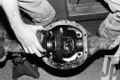
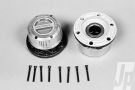
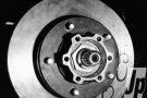
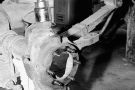
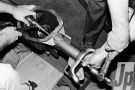
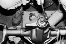
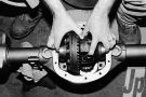
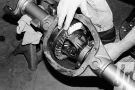
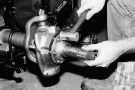
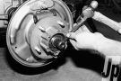
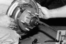
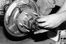
On a frontend, the centersection needs to be rebuilt, but the wheel bearings and steering knuckles complicate the job and need to be freshened up as we go along. And while we're at it, the factory plastic locking hubs get tossed and new Superwinch units are attached.

154 9901 Front Axles Rebuild light Line Dana 30 Rebuild Kit Photo 34752513 
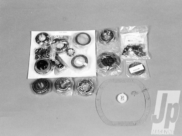
We like one-stop shopping, and Light Line of Louisiana offers just that with its Dana 30 front axle rebuild kit. In addition to the required carrier and pinion bearings and races, the kit includes a large assortment of pinion and carrier preload shims, a slinger, a yoke nut and seal, ring gear bolts, pattern grease, and Loctite. An instruction sheet on how to set up the ring-and-pinion is also included.

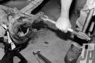
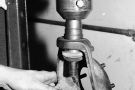
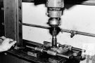
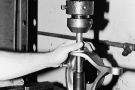
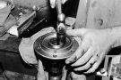
Rebuilding the frontend from wheel to wheel is fairly easy and only requires a few special tools. Except for some of the press work, which a machine shop should handle, all of this can be performed in your own garage with standard automotive tools and practices. Take your time and spend the bucks for good parts, and you'll have the job done right the first time

PhotosView Slideshow We tapped Superwinch for the locking hubs on the CJ. These premium hubs feature corrosion-resistant, painted and polished aluminum finishes, with a full-metal cap and body. The dial rotates from 2x4 to 4x4 in a quarter turn for positive engagement. With the wheels and tires off, remove the five or six bolts that retain the locking hub and pull it off. Depending on how the hubs were manufactured, a snap ring on the end of the axle may need to be removed. If you have a drum brake setup, take off the drum; on disc brake models the caliper needs to be removed. The exposed hex nut shown is removed with a big socket after the retaining tab behind it is bent away. Pull the retaining washer out, then the inner nut can be spun off, and the hub assembly can be removed. Remove the six bolts holding the caliper mount or drum backing plate and remove those parts. The spindle may take some force to be removed, and a dead-blow hammer is recommended. With the spindle off, the axleshaft can be slid out and cleaned up. To separate the drag link and tie-rod ends, remove the castellated nut and drive a pickle fork between the joint and the casting, as shown. The steering knuckles are removed by first removing the top and bottom nuts. Using a big hammer, rap against the axlehousing where the knuckle is, and the knuckle should drop away. Lots of penetrating oil may be needed depending on how stuck the joints are. Once the knuckle is removed, an adjusting sleeve is left in the top of the axlehousing, which unscrews with a special spanner wrench. The ball joints must be pressed out of the knuckle. If you don't have a press, you can do it with some creative hammer and punch work. Make sure to wear safety glasses at all times. First, the bottom joint is pressed out, then the top one is. Check the knuckle casting for cracks. Clean it, along with the other old parts. With the axles out, the diff cover is removed and the oil drained. The bearing caps are marked so they can be replaced the same way, then removed. Two large prybars can be used to remove the carrier. Have a machine shop remove the bearings.  Replace them, being sure not to damage the shims beneath them against the carrier. Use a micrometer to measure the shims and replace them with new ones, making sure they're placed in the same location as the old ones. The pinion nut is removed along with the yoke, and the pinion is pushed out of the housing. The inner race is punched out with a long punch, and the outer seal is pried out of the housing. Like the carrier shims, the shims under the inner pinion race must be measured and replaced with new ones. The outer pinion race is removed from the inside of the housing, either with a long drift or a specially made tool. The pinion also goes to the machine shop to have the inner pinion bearings pressed off. There are no shims underneath, but sometimes a slinger or a shield is there. If so, be sure to replace it with the same thickness and style for proper pinion placement and oil control. 
The Dana 30 has inner axle seals located near the carrier bearings on the inside of the pumpkin. The best way to remove them is with a long rod placed through the tube, and a few whacks of a hammer. Replacing the inner axle seals once the housing has been cleaned can be interesting. A proper size driver and assorted rods can be used to firmly seat the seals. It helps to have two people hold the multitude of tools during this procedure. Install the inner pinion shims and race, then insert the pinion. The outer pinion bearing and the preload shims are installed, then the yoke and the nut are installed. The seal is left out until the tooth pattern is verified-in case it all has to come apart for adjustment. Install the carrier assembly into the housing, which usually requires a bit of force from a dead-blow hammer. Check for a bit of backlash, install the carrier bearing caps and bolts, then torque to spec. White grease is supplied in the kit to check the tooth pattern, which is done at three locations on the ring gear. If the pattern is acceptable with the proper amount of backlash, install the pinion seal, gasket, and cover. Mark the unit "No Oil," until the final fill is done. Press new ball joints into the freshly cleaned and painted knuckles; install the bottom one first. If the joints have grease fittings, lube them and install the dust boots. Install the knuckle, and tighten the bottom nut to specifications. The top joint sleeve is adjusted with a spanner wrench to the specified torque, then the top nut is installed and torqued. The back of the spindle houses a needle bearing, which is usually dry and rusty. Remove this pocket bearing and replace it with a new one. A new plastic washer and a V-seal are installed next, although some early models are fitted with a brass washer and a metal-clad seal. Install the axle shafts into the housing, and place the spindle onto the knuckle, making sure the spindle seats all the way. The backing plate or caliper mount is installed, then the six bolts are tightened to specs. New races were installed in the hubs after the old ones were popped out and the housing cleaned. The new bearings are packed in a high-quality EP grease, preferably a high-temperature disc brake style. The inner bearing is installed and the hub seal tapped into place to retain it, then placed over the spindle. Install the outer bearing, which is also packed with grease. Install the inner thrust washer first, then the inner nut. A hammer and chisel can be used for adjustment, as shown, but for a better job, try to get the proper wrench. Adjust the inner nut tightly to seat the bearings, then back off a quarter turn. Install the outer washer and then the outer nut and torque it down. Rotate the hub and check for free play. If the hub rotates freely with no slop, bend the outer washer outward over the outer nut to prevent it from turning. Be careful not to crush the bolt holes when bending over the tab, since you can't thread the locking hub bolts into a squashed hole. Installing the new Superwinch hubs is about as easy a project as there is. After applying sealer to the gasket, the inner body slips over the axleshaft. The drive bolts are installed, preferably with lock washers and Loctite to prevent them from loosening up. The axle-end C-clip is popped onto the end of the axle. With the outer cap in the 4x2 position, the cap is placed over the locking hub. Small Allen screws are used to secure the cap to the body and need to be tightened enough to retain the cap but not strip the screws.