For decades magicians have been considered masters of illusion. With a slight of hand they can make things appear in a different light than would normally be perceived. When studying your hot rod for ideas on potential enhancements there’s a certain amount of magic you can infuse to bring a bit of optical illusion and speed of your own to the mix.
On a recent visit to the Rolling Bones Hot Rod Shop in Greenfield Center, New York, the team was preparing to fabricate a set of custom frame side covers for a 1934 Ford coupe that would not only bring a newfound sleekness to the car, but also create a look of it being channeled. This would also rid the car of its visual barb in highboy form of the break where the body meets the chassis. Getting started, Rolling Bones team member Keith Cornell selected 18-gauge steel for a rock-solid base, giving the cover plenty of strength seeing the car will be heavily raked and running very close to the ground. Assisted by two team members, a long length of flat steel stock was held in place just under the rocker panel abutting the outer frame side. Using a black marker, the body and frame curvatures were traced onto the steel, measuring 8 feet long and 3-1/2 inches wide. Note that additional length was added to accommodate for front and rear mounting points. To prepare the stock for trimming, 3/4-inch masking tape was used to outline the graceful sweep. In order to obtain a razor-sharp unwavering cut, Cornell selected 1/4-inch steel rod to act as a guide. He first clamped the rod to the end of the stock and tacked it in place using a Millermatic 35 MIG welder. He then removed the clamp, moved it forward, re-secured it, and MIG tacked once again, continuing the procedure till the arc was complete. The masking tape was then removed and while wearing safety glasses a Powermax 30 plasma cutter was used to make the cut to the tacked side of the rod. The rod was then removed using a small cutoff wheel followed by the welds and any rough edges being ground smooth using an air-driven grinder topped with a 50-grit disc. The panel base was then test-fitted and any fitment revisions to both the body and frame side were marked and adjusted to fit using a grinder and 50-grit disc with the base clamped to a workbench.
To create the first of five panel mounting points, a measurement was taken at the rear of the base section to allow it to bolt to the lowest fender mounting hole in the rear wheelhouse area. Cornell secured the section to a workbench using a Vise-Grip and a piece of angle iron and utilized a body hammer to add a 90-degree bend. The section was then test-fitted in place and marked for a mounting hole. An air-driven drill with a step bit was used to complete a 5/16-inch opening. The base was then clamped in place with Vise-Grips to keep it secure. Next, the top portion of the rocker panel was measured for three centered mounting points, respectively, at 1 inch, 17 inches, and 32-1/4 inches from the door hinge forward. A drill with a 1/4-inch bit was then used to set the initial holes. Care must be taken at this point for accuracy as you are drilling through three layers of steel. Since Cornell planned on using 5/16-inch steel brake tube to sleeve each mounting point and avoid any potential crush of the area when tightening, a 5/16-inch drill was used to further open the holes. A section of tubing was then snugly tapped into place and trimmed to fit with a cutoff wheel. The sleeves were then TIG-welded into place using a Lincoln Electric Precision 225 TIG welder. To protect the lower side body panels, a layer of duct tape was used, followed by any excess steel trimmed using a plasma cutter. The section was then deburred using a disc grinder and 50-grit disc. To give the rear adjustable mounting tab a nice clean look, it was trimmed with a nice arc and bolted into place. The adjustments will help greatly when dialing in the final body lines. Finally, to secure the base to the rocker, three weld nuts were TIG-welded to the inside of the panel base.
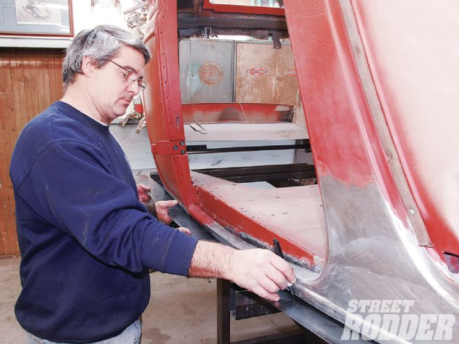
Keith Cornell of Rolling Bones held an 8-foot long by 3-1/2-inch wide section of 18-gauge steel to the frame side just under the rocker to trace the body and frame curvature.
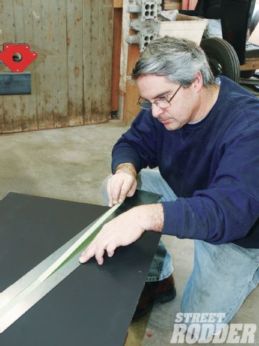
To mark the gentle sweep of the frame for the required trimming, 3/4-inch masking tape was used.
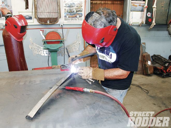
Rolling Bones used 1/4-inch solid steel rod that was then clamped in place and MIG-tacked in a gradual progression to follow the noted curve using a Millermatic 35 MIG welder.
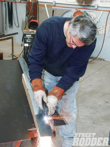
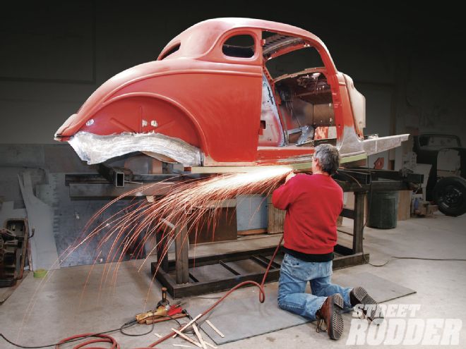
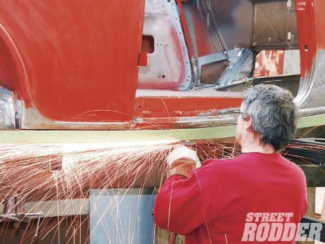
Using the 1/4-inch rod as a guide (while wearing safety glasses), a Powermax 30 plasma cutter made the incision to the tacked side of the rod, removing the unneeded portion of the panel base.
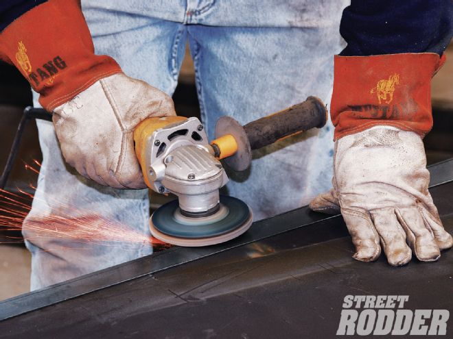
The 1/4-inch rod was then removed with a cutoff wheel and welds were ground smooth using a grinder topped with a 50-grit disc. The grinder was then used to deburr any rough edges.
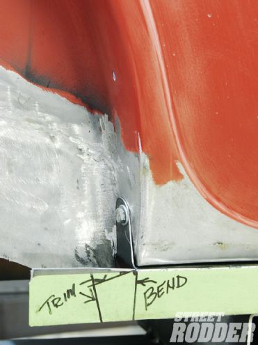
To anchor the rear of the panel in place, a mark was made for a 90-degree bend to utilize the lowest fender-mounting hole in the rear wheelhouse area.
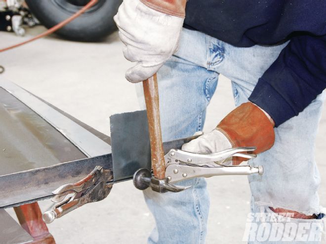
With the panel clamped to the workbench, Cornell used a body hammer to gradually work the 90-degree bend into place. It was then test-fit into position.
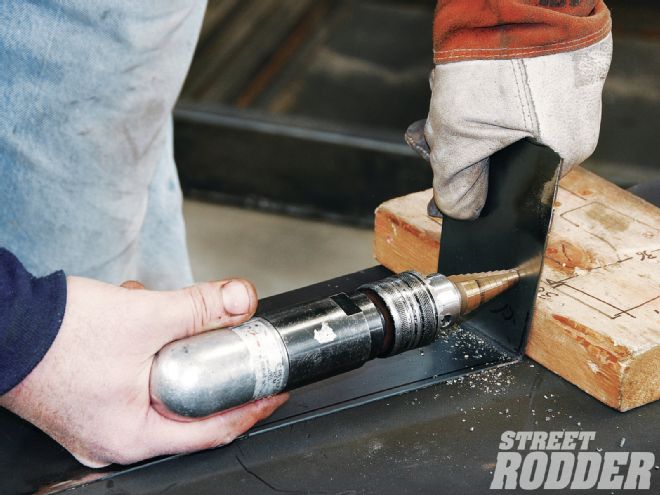
Using an air-driven drill with a step bit, a 5/16-inch mounting hole was then added to allow the unit to be mounted.
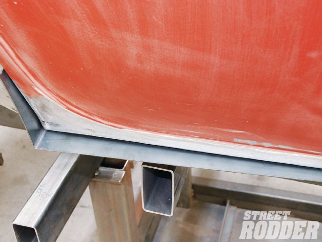
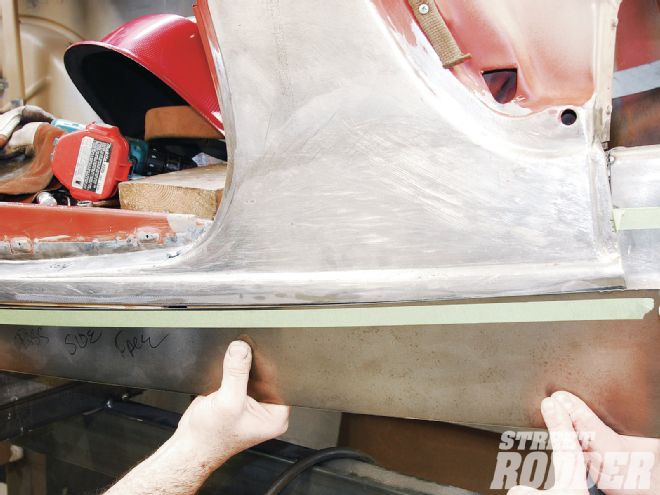
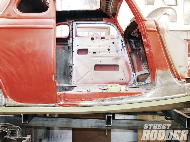
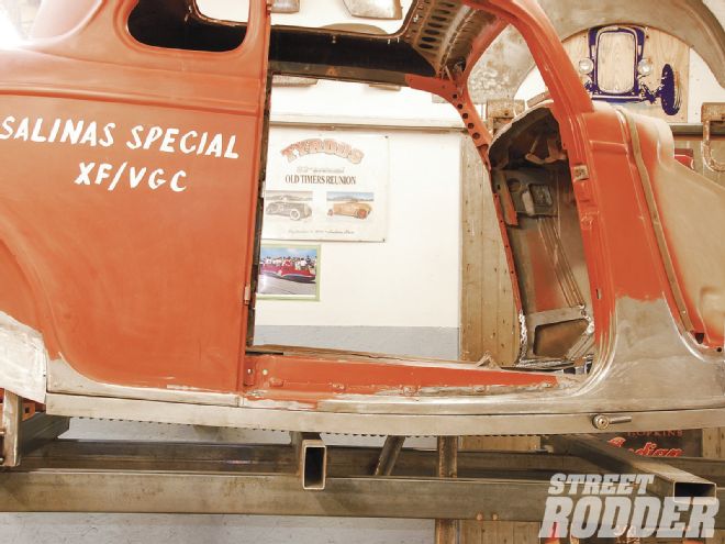
Here you can see the panel base mocked into place with the frame side adjustments.
And awaiting the trimming to match the body side lines.
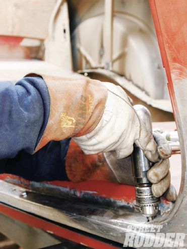
To properly anchor the unit in place, three equally spaced 1/4-inch centered pilot holes were drilled into the rocker panel. Note that you are drilling through three layers of steel.
The holes were then enlarged to 5/16 inches and a section of 5/16 steel brake tube was snugly installed for added strength. It was then trimmed flush with a disc grinder.
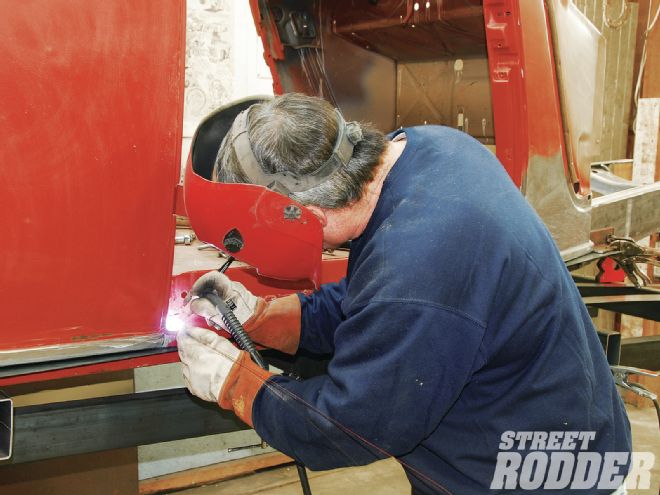
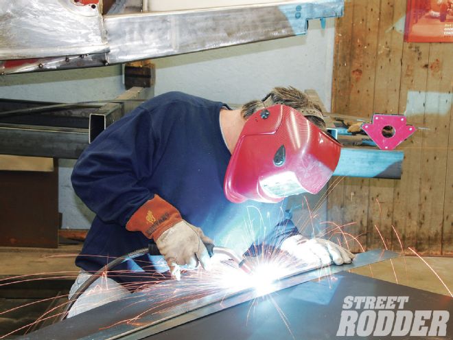
The sleeves were TIG welded into place using a Lincoln Electric Precision 225 TIG welder.
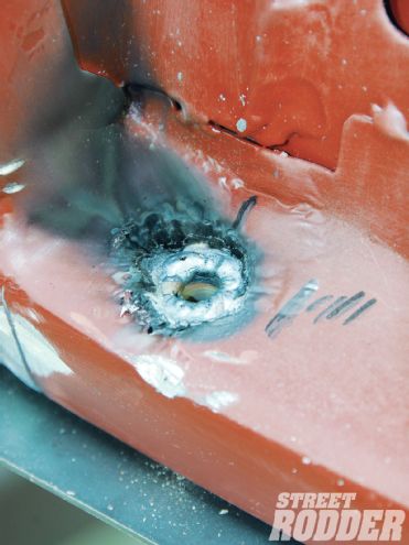
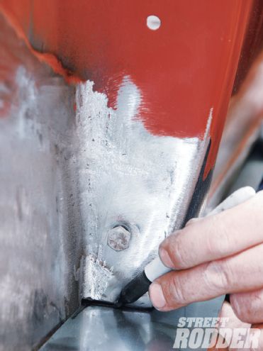
Here is the sleeve with the TIG welding completed. This will bring plenty of additional strength to the area once the cover is bolted into place.
A protective layer of duct tape was affixed to the lower body panels followed by Cornell removing the excess steel from the panel base using a plasma cutter.
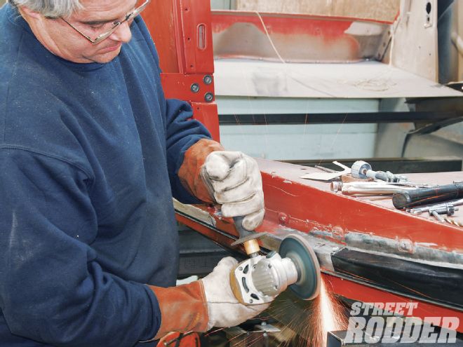
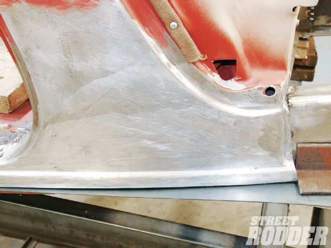
A disc grinder topped with a 50-grit disc was used to deburr the area and complete any final revisions to the sweep of the panel base.
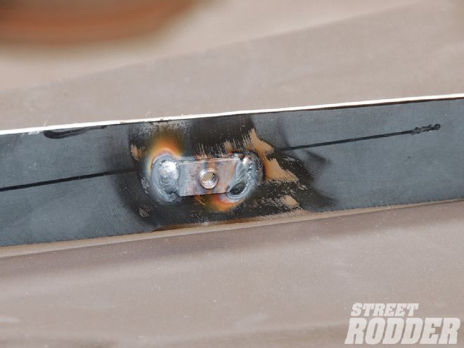
Three weld nuts were then TIG welded to the inside of the panel base to complete the mounting portion of the unit through the rocker.
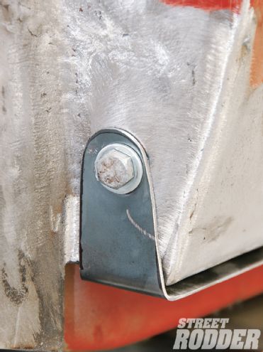
The rear mounting tab received a neat trim and is bolted in place. For proper fitment, plenty of fore and aft adjustment was worked into the design.
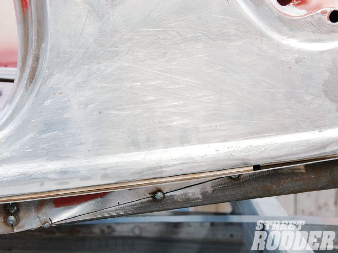
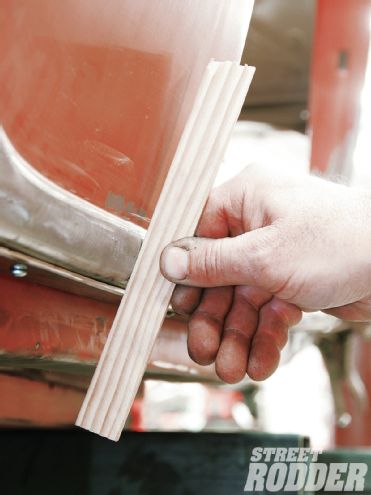
Paint sticks were used as spacers between the panel base and rocker bottoms to allow the side covers to be cleanly welded to the base.
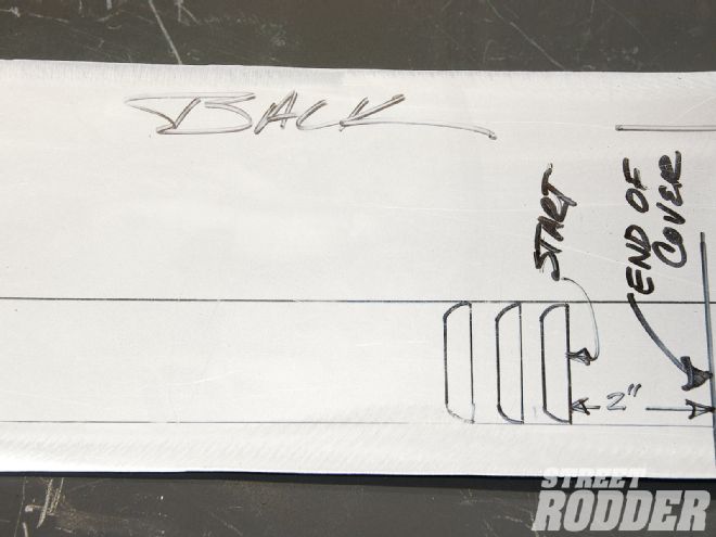
The side cover creates the magical impression of the car being channeled and needs to possess just the right lines to pull it off. In order to set up the base for TIG welding in the side cover, Cornell used simple paint sticks to create a slight buffer between the body and the base panel. In order to properly visualize panel flow, another paint stick section was used on the body side extending it down to illustrate how the side cover will need to follow the existing body curvature. With that done, he proceeded with team member Ken Schmidt to hold another 8-foot-long section of 18-gauge steel in place to mark its sweep to the base and confirm any needed trimming with 3/4-inch masking tape. With the side cover clamped to the workbench, a disc grinder with a 50-grit disc was used to trim the graceful line to perfection. The panel was then clamped into position and some initial TIG tack welds were set in place while using the paint stick to ensure the proper contour was being maintained to the lower bodyline. Cornell couldn’t stress enough the importance of dialing in the contour now to avoid time spent to correct something down the road. To dial in the final curvature, a number of relief cuts were made to the panel base with a cutoff wheel, allowing just enough movement to make the needed adjustments. The cuts were then TIG welded in place and ground smooth with a grinder and 50-grit disc. With the panel centered and everything set to go, there was a particular welding sequence to follow, starting with the center and fanning out from left to right, matching and cooling each weld as you go. With each weld, Schmidt checked the contour to ensure a proper balance was being met. Once the TIG welding was completed, Cornell measured the height required for the side cover, noting it was 2 inches. A section of 2-inch masking tape was then run across the top of the panel, illustrating the sweep and the amount needing to be trimmed off. Using a plasma cutter the excess was removed and then deburred with a grinder and 50-grit disc. At this time the rear mounting tab side was trimmed and bent into position and the final adjustable mounting point for the front of the panel was trimmed and bent into position. To secure it in place the framerail was then drilled and tapped for a 1/4-inch coarse thread bolt.
The 6-inch-wide bottom panel was then cut and trimmed in the same fashion as the base and side panels from 18-gauge steel. Prior to final welding, Schmidt laid out a flowing sequence of 2-inch louvers to give the bottom side a racy feel. Once completed, the panel was TIG-welded into place and all welds were ground smooth using a grinder and 50-grit disc. The completed panel added plenty of sleekness to the coupe, removing any visual barbs that once were present. The illusion of channeling is just icing on the cake.
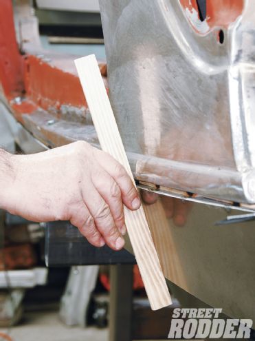
With a paint stick, Cornell illustrates how the side covers will follow the curvature of the body side once welded in place.
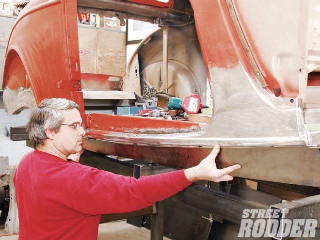
Using the same formula as on the panel base for fitment, the trimmed 18-gauge steel side cover is mocked in place showing its long sweep and curvature.
Team member Ken Schmidt held the side cover in place while a 3/4-inch tapeline was pulled to confirm the final trimming. A grinder and 50-grit disc completed the job.
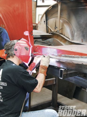
Cornell TIG tacked the panel in place, starting at the center and moving outward from side to side while checking the contour with the paint stick after each weld.
To complete the contour, a number of relief cuts were required to the panel base using a cutoff wheel. The incisions were then TIG welded and later ground smooth with a grinder and 50-grit disc.
The paint stick doesn’t lie; check out just how nice the contour of the body side matches the side cover. This should be perfect from front to rear and takes time to accomplish.
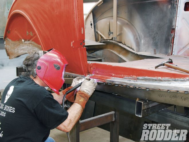
With the contour dialed in, Cornell continued with the TIG welding to the side cover. Note that an air gun was used to cool each weld prior to proceeding to avoid panel warp.
Since the exposed frame side was 2 inches tall, 2-inch masking tape was used from the top edge of the base down to mark the cut line for the side cover trim.
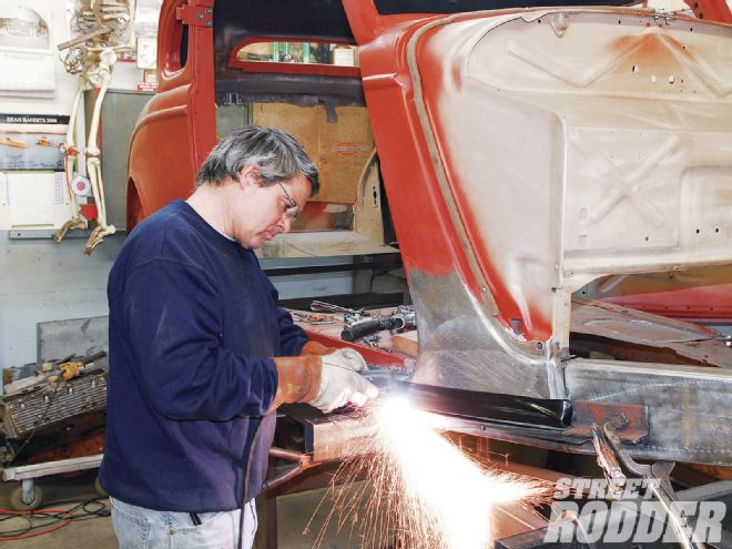
A cutoff wheel was used to remove the unneeded portion of the side cover, starting from the rear and moving forward. The area was then deburred with a grinder and 50-grit disc.
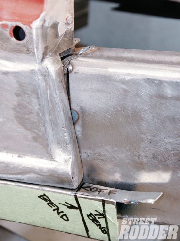
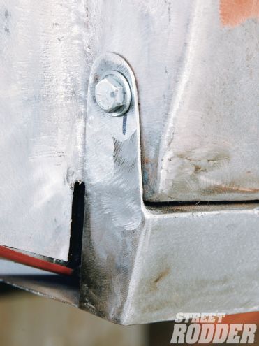
With the side cover welding finished there was still a bit of fabrication required to complete the side portion of the rear mounting tab, as seen here.
Here you can see just how nice and clean the adjustable rear mounting tab looks with the side cover modifications completed.
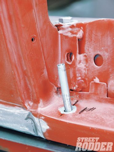
The front of the frame cover required two bends and a bit of trimming.
Some final welding to create a nice clean mounting tab to the side of the framerail.
Cornell used a plasma cutter to create the bottom panel from 18-gauge steel the length of the side cover and 6 inches deep. Schmidt then laid out the 2-inch louvers to be punched.
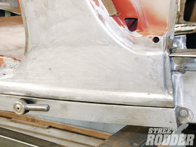
With the front adjustable mounting tab complete and accommodations for the rod end added, the side cover is looking wicked.
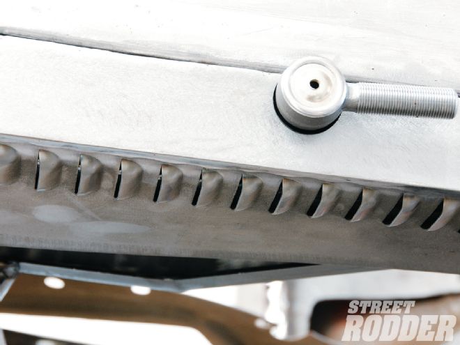
Check out how seamlessly the side cover wraps under the frame side accented by the long flowing row of 2-inch louvers.
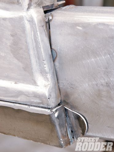
The final wrap of the rear mounting tab combined with the lower panel give the finished product a great look.
The finished side cover gives the car a newfound sleekness and an illusion of the body being channeled. The success is all in the details.