It’s not very hard to improve old Fords. As economy cars they were built for price and durability and not extreme performance. On the other hand it’s intensely difficult to improve them as elegantly and economically as Ford’s engineers created them. At the very least it’s wishful thinking to expect any valid improvements to simply bolt on.
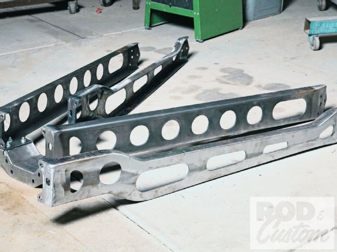 1 Industrial Chassis offers the legs in two flavors: straight for cars with flat floors and dipped for cars with dropped floors.
But Steve Szymanski at Industrial Chassis just may have done the impossible with three kits for the ’32 Ford. One endows the frame with the rigidity that the ’33-and-later chassis enjoy. Another adds a master cylinder to the crossmember. The third one makes the ’32 pedal assembly operate like the one in the ’39 Ford. And more than transform the car, these kits do so without any cutting, welding, or drilling. They all bolt in through existing holes.
The frame kit transforms the ’32 Ford’s noteworthy K-member into a modified X-member. The X-member stands as one of the strongest, most economical designs in perimeter-frame technology. It derives respectable strength from a minimum amount of material by orienting shapes by their strongest dimensions and by distributing load over a greater area. Ford adopted it in 1933 and, as testimony to the idea, stuck with the same basic design until 1948. Actually that’s not entirely true; Ford (and other manufacturers) fortified topless cars’ frames with X-members for generations thereafter.
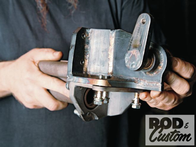
 2 Both center supports increase the structural integrity of the frame by making a C-channel from the crossmember. The one in the background also doubles as a mounting point for split wishbones.
The X-member kit consists of three parts: two diagonal legs and a center support that ties their lower edges into the existing crossmember’s bottom flange. Industrial Chassis offers the legs in two flavors: straight for cars with flat floors (roadsters, standard coupes, and most sedans) and offset for cars with dropped floors (DeLuxe coupes and Victorias, among others).
It offers two center-support variations: plain and “winged”. The plain variation suits cars that use the stock, un-split wishbone in the stock socket (the kit doesn’t interfere with the stock mount) or cars that have existing split-wishbone conversions.
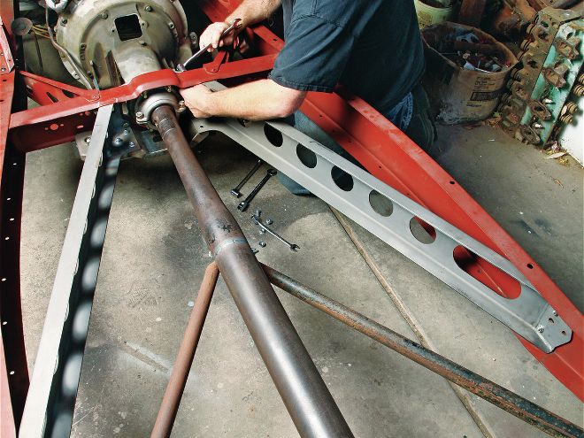
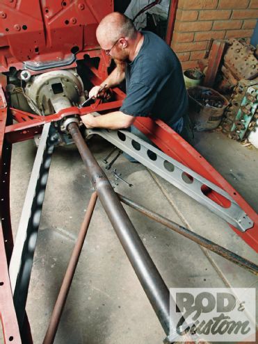
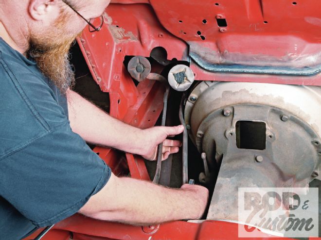
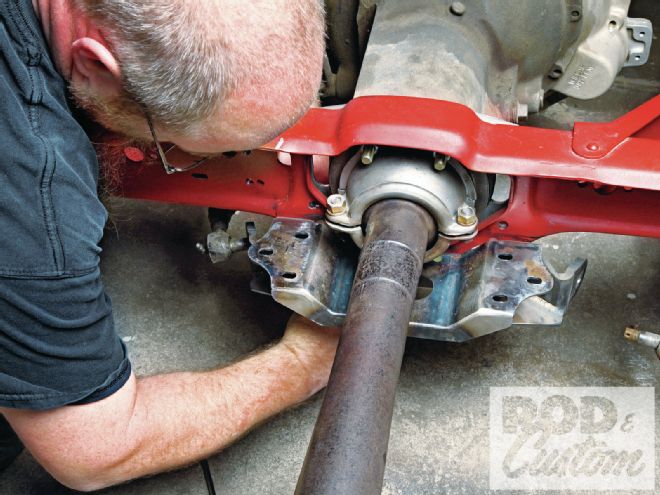 3 Installation begins with the center support. It fastens to existing mounting holes in the crossmember.
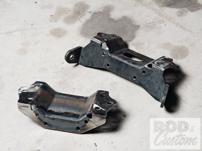
The party piece, however, is the winged variation. It features a thicker vertical plate that descends below the crossmember and bends forward as two “ears” on either side of the transmission. Those ears serve as split-wishbone mounts; Industrial Chassis drills and reams each one to accept a conventional Ford tie-rod end. Splitting the wishbone with conventional bungs and using early Ford tie-rod ends lands the studs right at the tapered holes. The modest split spreads the wishbone legs wide enough to accommodate most non-Flathead oil pans (this car boasts a Hemi) yet not enough to cause the suspension to bind excessively.
To test the kit’s effectiveness Szymanski devised a rig that measures how much the frame deflects under a given load. The rig supported the bottom of the frame at four points: at the cowl and at the rear-fender mounting holes. He clamped the frame to the rig then hung a 50-pound weight from a 6-foot-long tube that he projected from one of the front framehorns.
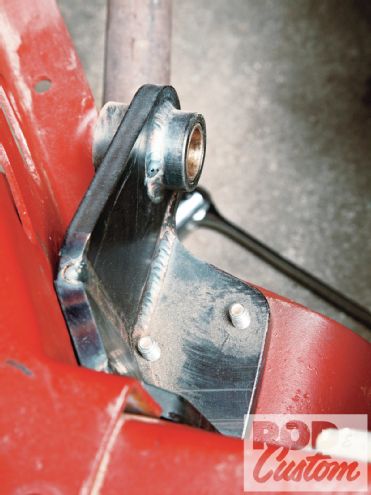
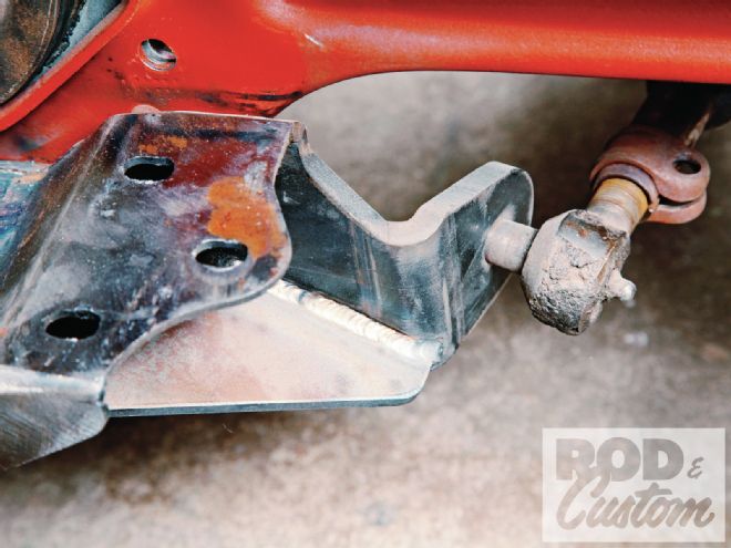 4 Szymanski makes the optional split-wishbone center support from thicker material and reams it to accept a Ford tie-rod end. It splits the wishbone legs for pan clearance yet keeps the ends as close as possible to minimize bind.
He used a conventional boxed chassis with a tubular crossmember as his baseline. “The frame deflected about a 1/2 inch,” he notes. He performed the same test with a completely stock (un-boxed) frame that he modified with only his X-member kit. “It deflected about 5/8-inch,” he observes.
Yes, that’s 1/8-inch more than what the conventional frame flexed but bear something in mind: the baseline was a chassis boxed from stem to stern and augmented with a complex tubular center crossmember ala contemporary street rod practice. His design, on the other hand, is nothing more than two channels, a bent plate, and a handful of bolts that fasten to existing holes. What’s more, his kit looks the part of an old Ford design, adds a fraction of the weight of the boxing plates and tubes, and installs in a matter of hours with the most basic hand tools. In fact this kit could be added to a completely intact car.
“I’m not going to say that the stock frame doesn’t flex at all up ahead of the K-member but it’s not as bad as people think,” Szymanski clarifies. “What really flexes is the area between the K-member and the rear-fender mounting holes. It’s an S-shape so it bends really easily. This makes a big difference, though.”
 5 Shown here are two things: the pedal mount that Szymanski offers on a modification basis and the master cylinder bracket kit with an early Ford master cylinder attached. Note that Industrial Chassis offers the bracket for later dual-circuit cylinders too.
Granted the utility of this specific design has its limitations, Ford designed the K-member’s crossmember to accommodate the ’32 transmission mount which, of course, was designed for the small ’32-48 passenger (and ’49 pickup) case. Over the years people have modified the crossmember to accommodate various other transmissions (Cad-LaSalle, Packard, Olds, and early Econoline come to mind, and the Borg Warner T5 has gained popularity recently) but their use requires considerable fabrication and that sort of defeats the kit’s bolt-in appeal.
Adhering to the bolt-in edict limits this kit’s utility to traditional-style builds but that’s of little consequence; generally speaking only a historically inclined builder would labor to use a K-member in the first place. But for that application it would be pretty difficult to top the elegance and effectiveness of this kit. It first and foremost lends a great deal of structural integrity to a legendary frame and it looks the part of an old Ford design.
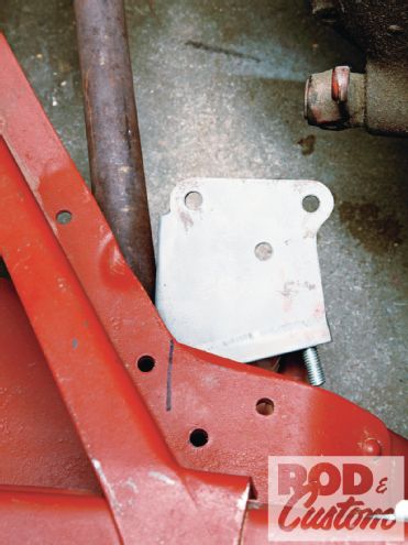 6 The master cylinder bracket fits to the bottom of the crossmember. It fastens to the same holes that the stock pedal cluster uses. This bracket, when combined with a ’32 pedal with a relocated brake lever or a stock ’39 pedal, is the core of a hydraulic conversion.
 7 The stock ’32 pedal bracket or Szymanski’s version fits to the top, thereby sandwiching the crosspiece between it and the master cylinder bracket. Tapped holes in the bracket eliminate the need for nuts.
Pedal Assembly And Master Cylinder Mount
Without a doubt Industrial Chassis’ X-member conversion is one of the most novel kits ever produced for the ’32 Ford chassis. But it’s not the only one. Szymanski also developed a group of modifications that make the pedal assembly more user friendly.
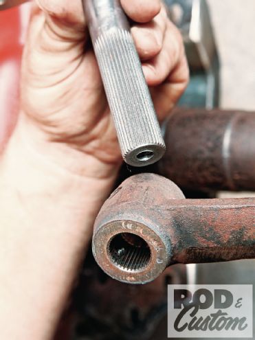 8 As part of his pedal-assembly modification, Szymanski reams the existing clutch arm and welds a broached sleeve in its place. It engages a similarly broached shaft. That shaft pivots in a bushing in the bracket.
Of them the bracket that adds a hydraulic master cylinder will find probably the most fans. As in the case with the X-member, it simply bolts to the crossmember through existing holes. Industrial Chassis offers it in two variations: one to mount a ’39-48 Ford master cylinder and another to mount a later dual-circuit master cylinder. The kit’s installation still requires relocating the brake-rod tab to the bottom of the pedal boss (which Szymanski can do as an option) but it otherwise eliminates a considerable amount of fabrication.
The pedal bracket isn’t as much a kit as a modification. It requires existing parts, specifically yours. But the result is no less profound: Szymanski modifies the pedal assembly to operate as it does in the ’39 Ford. It does so in the sense that the modified pedal cross shaft doubles as part of the clutch-release mechanism.
He does it by reaming the existing clutch pedal boss and welding a broached sleeve in the hole. He then welds an arm on the end of a similarly broached shaft. That arm aligns with the arm at the end of a more common and affordable ’39-style throw-out lever or Industrial Chassis’ fabricated version. It’s a fair bit of work but it’s a lifesaver: It eliminates the need to score a potentially hard-to-find piece of hardware, the ’32-only clutch-release arm that fits on the throw-out shaft in the bell housing. Given the amount of core parts—parts that have gotten somewhat hard to find—it’s understandable that Szymanski chooses to offer this assembly as part of a modification rather than as a kit.
 9 The modified pedal assembly installs as stock, thereby preserving the stock pedal locations.
It’s the modifications’ utility that makes them so relevant. Each dramatically improves the way an old Ford performs. Then again, a lot of kits can claim the same thing. This industry was built upon them after all. But not many of those kits do it with the same Ford-like elegance as these do.
Ford was notorious for changing the ’32 Ford throughout its limited production to amend various shortcomings, a practice that resulted in special parts that were unique to manufacturing date if not plant. Judging by the way they fit with the existing design it would be an easy case to make that these were parts that Ford could’ve made. And judging by the way they work it would be an even easier case that they’re parts that Ford should’ve made.
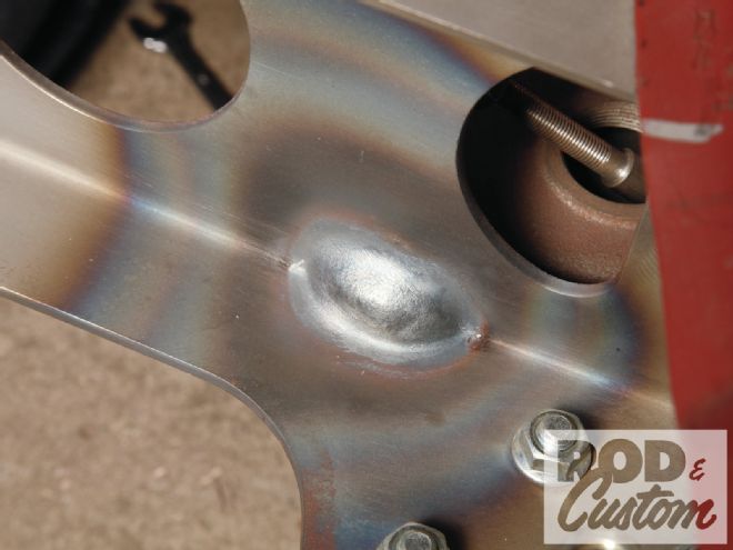 16 Master cylinder clearance requires a dimple in the left leg. Other master cylinder designs may require a larger dimple or possibly trimming.