Instrument panels are among the more befuddling components of the average classic Mustang. However, there’s really nothing to your Mustang’s instrumentation or lighting; the average Mustang instrument cluster is basic automotive electricity at work. It is also mechanical if you’re talking about the speedometer, which will not be addressed in this article. The ammeter indicates the flow of current either positively (charging) or negatively (discharging). A speedometer is little more than a whirling magnet inside a shell, which is tied directly to the speedometer needle. The faster it whirls with corresponding vehicle speed the higher the needle reading. All other instruments, including tachometers, are electric.
Temp, Oil, Fuel
Your Mustang’s fuel, temperature, and oil pressure gauges all work on the same principle—resistance to current flow to ground and how that affects needle position in the gauge. In fact fuel, temperature, and oil pressure gauges are all the same instrument fitted with different faces and senders. Each of these instruments has a bi-metallic spring-loaded needle with a heating element (resistor). Needle position on a gauge is affected by current flow across the gauge to ground at the sender. When resistance at the sender is low and current flow is high to ground, the instrument will read high. By contrast, when resistance to ground at the sender is high and current flow is low, the gauge will read low. Sending units, be they temperature, oil pressure, or fuel level, are all variable resistors. They control current flow to ground, which affects needle position at the gauge.
How does resistance affect the way a gauge reads? Heat: each gauge has a bi-metallic spring, which is affected by temperature, tied to the needle. Alongside the bimetallic spring is a resistor. As current flows through the resistor, heat is generated. When current flow increases to ground via the sender, the resistor gets hotter causing the needle to move toward maximum. When your fuel tank is full, resistance to ground via the float resistor is low causing the gauge to read “F”. Temperature and oil pressure work the same way. When coolant is cold, resistance to ground at the sender is high with low current flow and the needle at “C”. As the engine warms, resistance at the sender becomes lower and current flow becomes high. The gauge’s resistor becomes warmer and the needle moves higher. Same is true for the oil pressure gauge. Oil pressure against the sending unit’s diaphragm reduces resistance to ground causing the gauge’s resistor to heat up moving the needle toward “H”.
On the back of each instrument cluster is a voltage limiter, also known as a voltage regulator. The voltage limiter limits instrument voltage from the ignition switch to 5.0-volts. If you applied a full 12-14 volts to the instruments they would become toast in short order. Instruments must have a regulated 5.0 volts. The voltage limiter is actually a small buzz box, which cycles current on and off rapidly to get 5.0 volts. It operates in a similar fashion to a turn signal flasher, with a temperature-sensitive bi-metallic strip that gets hot opening and closing the circuit rapidly to maintain 5.0 volts. Voltage limiters fail two possible ways. They open the circuit (burned or missing contact points) rendering instruments inoperative or they seize closed (fused together) shoving all needles to maximum. If your temperature, oil pressure, and fuel gauge all go to maximum you probably need a new voltage limiter.
Ammeter
The humble ammeter seemed right for the time, but we would have been better served with a voltmeter. Ford ammeters never seem to move. Turn all lights and accessories on, with the engine off, and the needle doesn’t move. Rev the engine with no electrical load and the needle doesn’t move. In truth, your Mustang’s ammeter has never functioned because most of them burned up when they were new. Ammeters failed because they were always under capacity, yet responsible for handling your Mustang’s electrical load. The power to all of your Mustang’s electrical components travels through the ammeter. If that doesn’t give you pause perhaps this will—ammeters can and do start fires. If you were lucky, your Mustang’s ammeter burned up and never functioned again. Those unlucky had Mustangs burn to the ground because there was no circuit protection for these instruments, which are constantly live.
When you have your Mustang’s instrument cluster removed for service, it is suggested you disconnect and bypass the ammeter, especially if you’re going to a single-wire high-amp alternator. Bypassing the ammeter renders it inoperative, but safe. There are inductive type ammeters in 1965-1966 Mustangs unaffected by the shortcomings just mentioned. However, if you have a direct-connect ammeter, disconnect and bypass it.
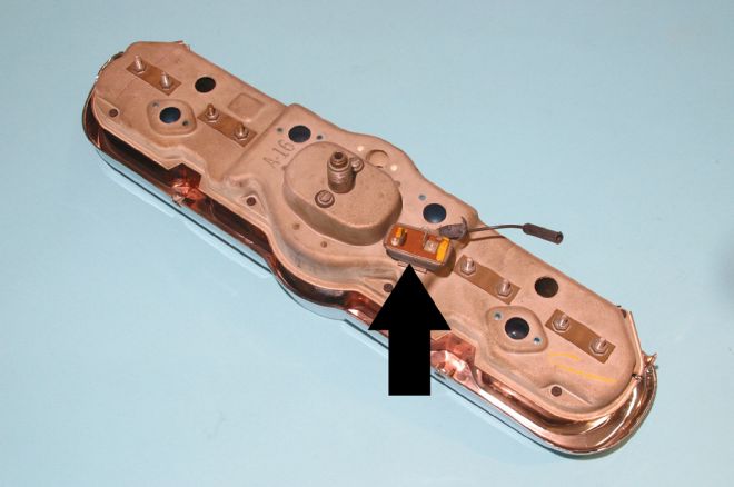
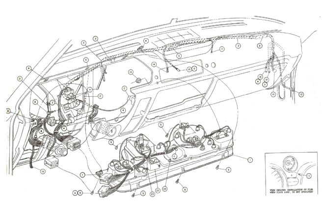
01. This is your basic 1965-1966 Mustang instrument cluster void of its wiring because the wiring is in integral part of the main wiring loom behind the dashboard. The instrument voltage limiter (arrow) limits voltage to 5.0 volts.
02. The 1965-1966 Mustang instrument cluster’s sockets and connections are all a part of the main wiring harness, which makes removal and installation challenging. If you follow color coding in your Ford Shop Manual, installation becomes easy. We have also used a strip of tape across the top of the cluster and a permanent marker to label where all the wires go.
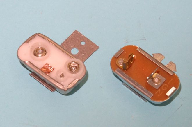
03. There are two types of voltage limiters used in classic Mustangs. On the right is the voltage limiter used from 1965-1968 with connector pins. On the left is the button type voltage limiter for 1969-1978 Mustangs with printed circuit instrument panels. Power to the voltage limiter comes from the ignition switch and is live only when the ignition is on or in the accessory position.
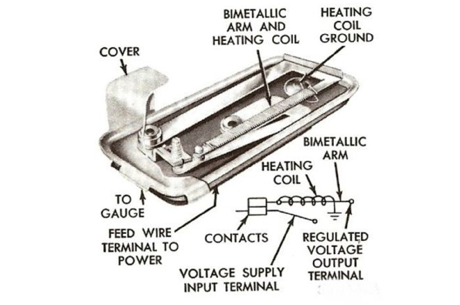
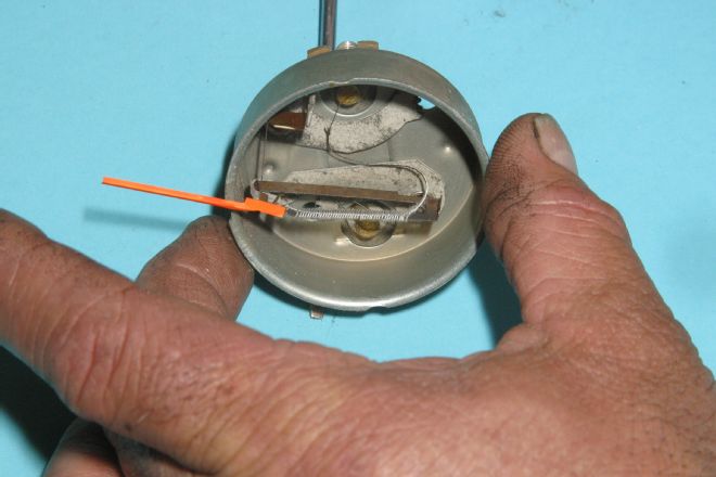
04. Here’s a good look at how a voltage limiter works in holding instrument voltage to 5.0 volts. It does this via a rapid-fire circuit breaker process, buzzing off and on. It does this with a bi-metallic arm and a heating element. The heating element acts on the bi-metallic arm causing contact points to open and close maintaining the constant 5.0 volts.
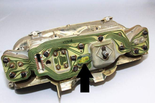
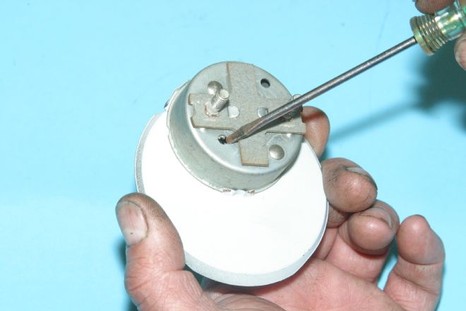
05. Here’s where you can expect to find the instrument voltage limiter on the 1967-1968 Mustang cluster. Power comes from the ignition switch through the voltage limiter to fuel, oil, and temp gauges.
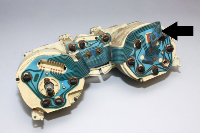
06. The 1969-1973 clusters have a button style voltage limiter that buttons to a printed circuit like a 9-volt battery does in an electronic device. It is impossible to get it backwards.
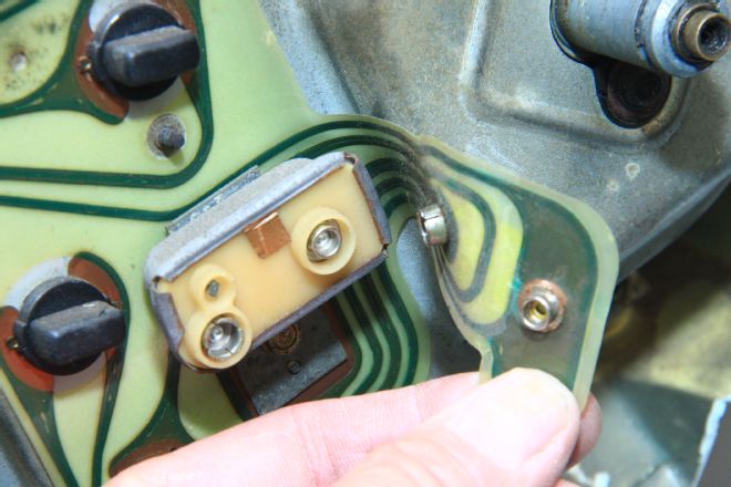
07. Here’s a close-up of the printed circuit button connector. You can expect the same scenario on the 1974-1978 Mustang II.
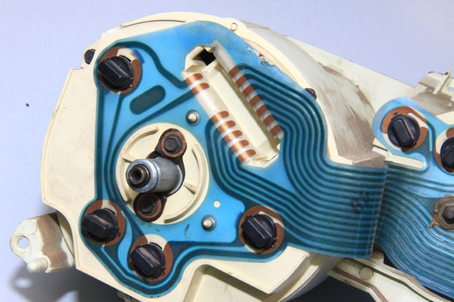
08. General Motors used printed circuit instrument panels long before Ford did. Ford switched to printed circuit instrument panels in 1969. A central multiplex plug inserts here to direct power to and from the cluster. We’re pretty convinced Semon E. “Bunkie” Knudsen brought this idea from GM when he joined Ford in 1968. The printed circuit cluster took just seconds to install during vehicle assembly.
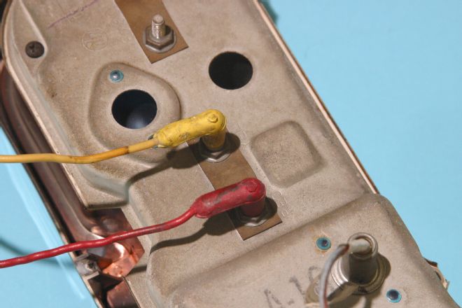
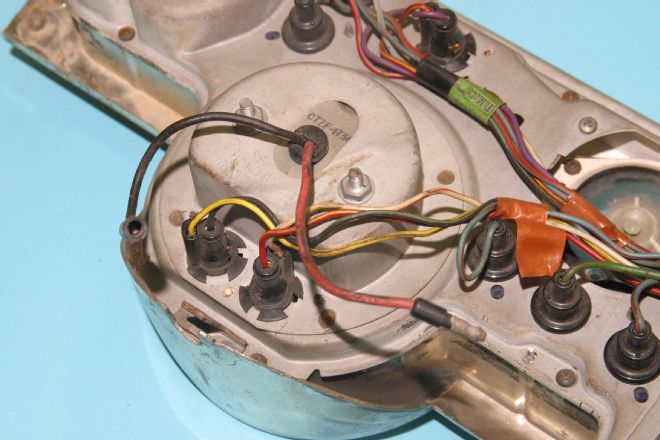
09. Although ammeters were commonplace in the mid-1960s, they were never a good idea mostly because they were not up to the job for which they were intended. Power to your Mustang’s electrical system is routed via the ammeter where it arrives first at these red and yellow connectors. This is what you can expect to see for 1965-1968. It is remarkable to us just how lame this approach was because it was under-duty with just not enough capacity.
10. Here’s one approach Ford used for the ammeter for 1965—an inductive style ammeter.
11. Here’s why the Mustang’s ammeter was a bad idea. Because Ford ammeters were underrated, they overheated and burned up in the first few months of operation. This is why most of them do not work. When you perform instrument cluster maintenance, disconnect and bypass the ammeter using the same gauge wire for a jumper.
12. Here’s a gauge from a 1965-1966 Mustang. Fuel, oil, and temp gauges all look like this. Needle movement happens as a direct result of current flow across the resistor shown here. A bi-metallic strip attached to the needle is affected by current flow across the resistor, which is a heating element. The greater the current flow to ground at the sender, the hotter this resistor gets, causing the bi-metallic strip to move the needle. With the gauge disconnected, adjust the needle to the “E” or “L” depending upon the instrument. Keep in mind these gauges are not linear meaning they are not spot-on accurate.
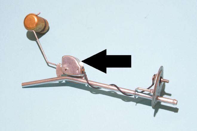
13. The fuel sending unit and pick-up located in your gas tank is a variable resistor to ground. When the tank is empty and the float is at the bottom, you have high resistance to ground and low current flow across the fuel gauge with a needle at “E”. With a full tank, resistance is low and current flow is high rendering the needle at “F”.
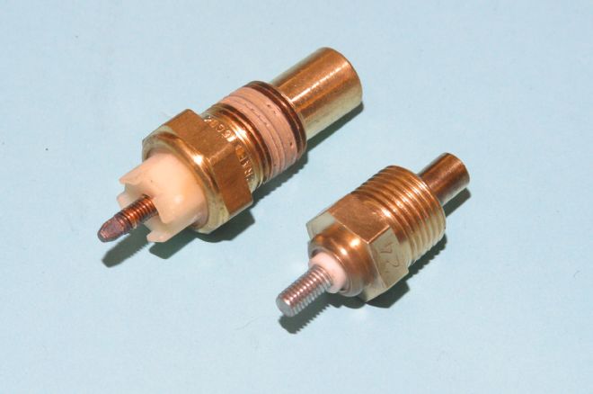
14. Here are two examples of coolant temperature sending units. There are two basic types of sending units: warning light and gauge. Warning light types normally have two pins. Gauge types are one pin to ground. Inside the sender is a variable resistor. Engine cold we have high resistance to current flow to ground and a needle on “L” or Low. As the engine’s coolant warms, resistance decreases to ground and the needle moves toward the middle of the gauge.
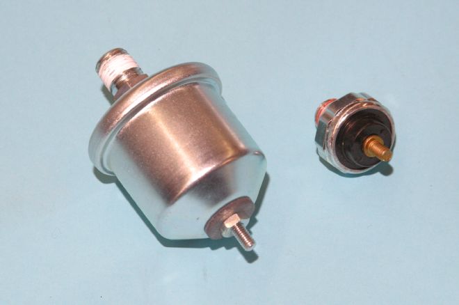
15. Here are two types of oil pressure senders—gauge (left) and warning light (right). The gauge type sending unit is a variable resistor to ground. Engine off or with no oil pressure we have high resistance to ground and the needle takes a nap. Engine started with oil pressure causes a decrease in resistance to ground and the needle moves. When oil pressure senders fail we get no reading or maximum. The oil pressure warning light sender is a simple on/off switch. No oil pressure and the switch is closed, illuminating the warning light. With oil pressure, there’s no continuity and no light.
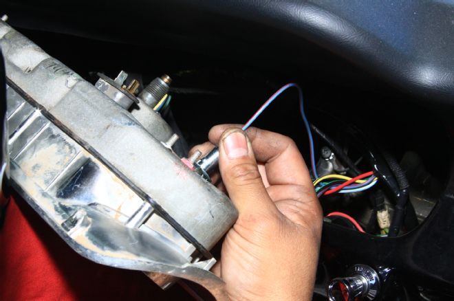
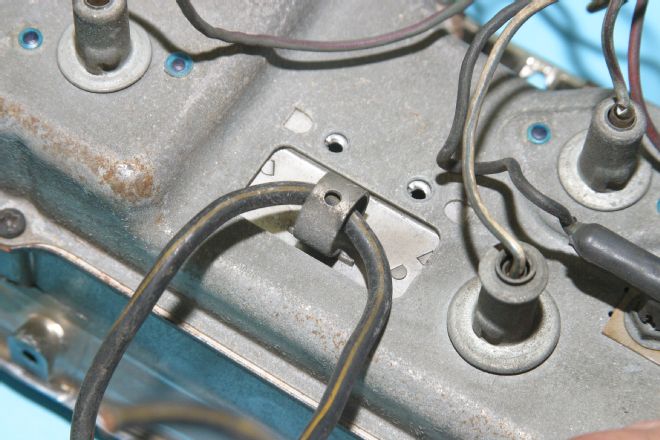
16. For 1965-1966 cars, instrument lighting and plugs are integral to the main wiring loom. Beginning in 1967, Ford went to a separate instrument panel wiring harness that plugs into the main harness, which is what you see here. The best way to access instrument wiring and speedometer cable on the 1967-1968 Mustang is to remove the climate control panel and reach through.
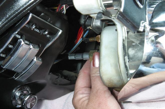
17. Once the speedometer cable is disconnected, cluster removal is easy.
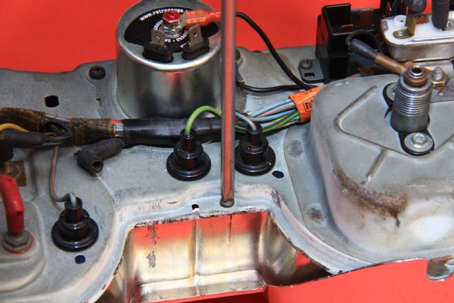
18. Here’s a 1967-1968 gauge cluster with tachometer (red and black leads) and warning lights. Black is ground and red is trigger.
Restore Your Instrument Panel
California Mustang has everything you’re going to need to restore a classic Mustang instrument panel, plus plenty of technical support if you hit any snags along the way. We’re going to take on a 1967 instrument cluster and show you how to improve its function with fresh parts including LED lamps and a new voltage limiter.
19. With the cluster safely positioned on our workbench, the bezel-to-cluster screws are removed using a #2 Phillips screwdriver.
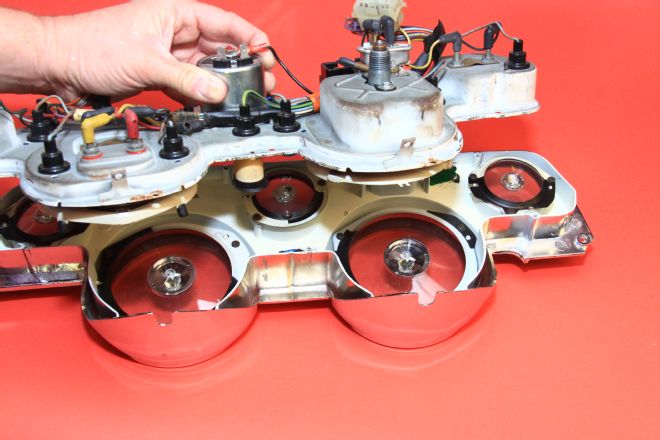
20. The bezel and cluster are carefully separated. Light diffusers must be carefully handled to ensure they don’t get damaged.
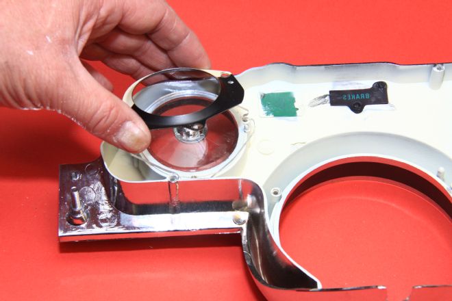
21. Lens diffusers are removed next with a Phillips screwdriver. They will be transferred to the new California Mustang bezel.
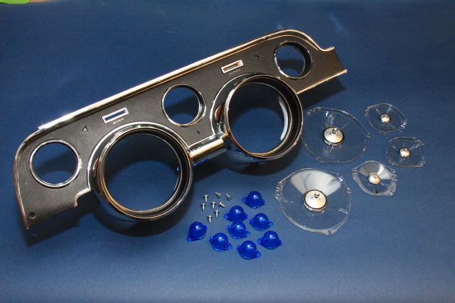
22. Check this out—California Mustang offers everything you’re going to need to restore a classic Mustang instrument cluster. Here, we have the standard 1967 “camera case” finish bezel, lamp gel caps, screws, and lenses. This is really a nice piece manufactured to high standards and priced reasonably.
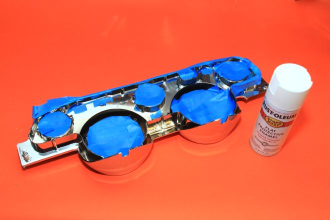
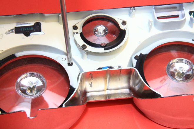
23. To improve instrument lighting distribution, mask your bezel properly to protect chrome and painted surfaces, and then paint inside reflective surfaces with Krylon flat white.
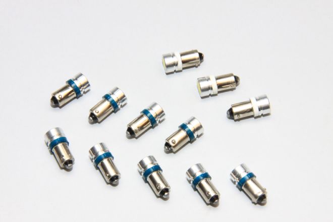
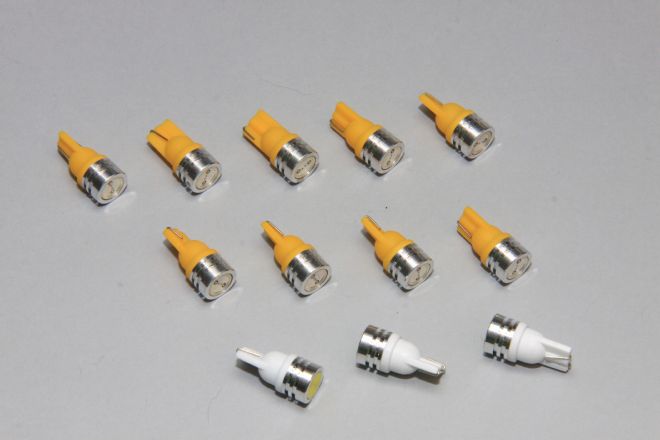
24. California Mustang stocks high-tech LED lamps for classic Mustang instrument panels, which is a nice improvement over those Thomas Edison-era #1895 lamps. These LED lamps come in a variety of colors based on what you’d like to see at night in your Mustang cluster. You can use these lamps with the green gel caps or remove the caps entirely.
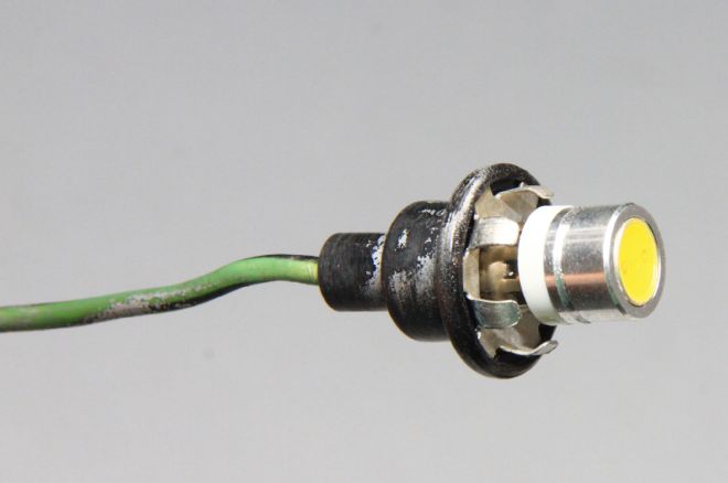
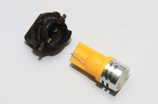
25. Here’s the California Mustang LED lamp in a 1965-1968 Mustang socket. Just press and turn to seat. These LED lamps run cool and virtually never burn out. They deliver a more brilliant electric “white” hue, which feels different than tungsten light.
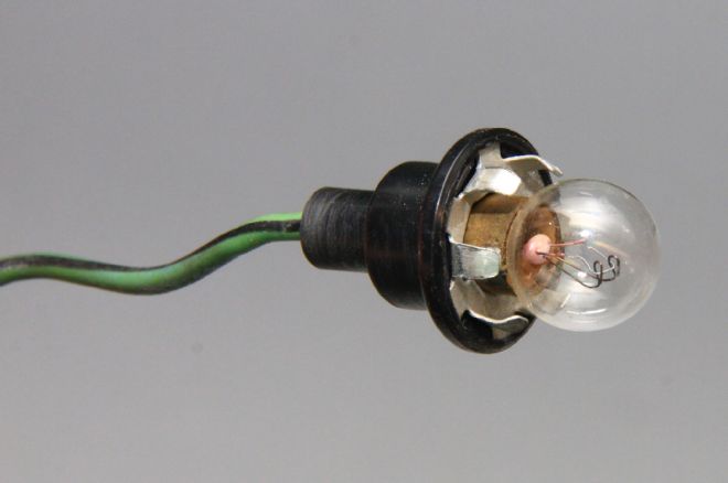
26. Here’s a 1967 Mustang standard cluster with #1895 tungsten lamps.
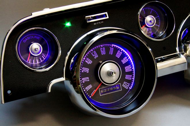
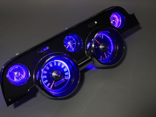
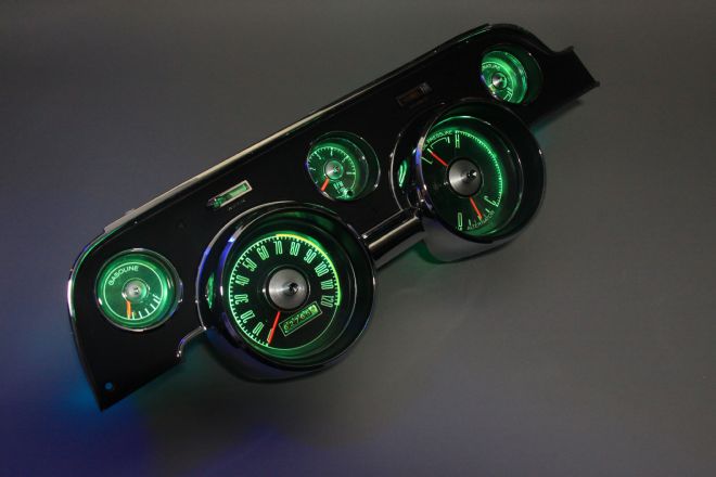
27. Look what happens when we light this thing with California Mustang Blue LED lamps. When we keep the green gel caps, we get an iridescent purple glow that’s a knockout. LED gives you the opportunity to experiment.
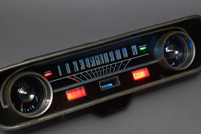
28. Here’s a standard 1965 cluster with blue LED lights and LED warning lamps. Wow!
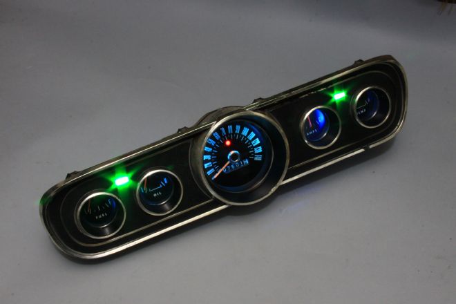
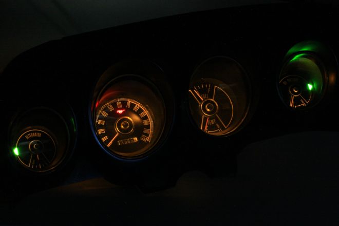
29. Check out the 1965-1966 five-dial cluster with blue LED, green LED turn signal, and red LED high-beam lamps. These LED lamps make a vanilla cluster pop.
30. The 1969-1970 printed circuit cluster uses #194 bulbs, which press in. Keep in mind these press-in LED lamps light only one way. If you install them backwards, they don’t light.
31. Look at this 1969 cluster with the California Mustang LED lamps. You may go with any color you’d like. We went white here with green turn indicators and red in the high-beam. These LED lamps add such an exciting dimension to classic clusters.