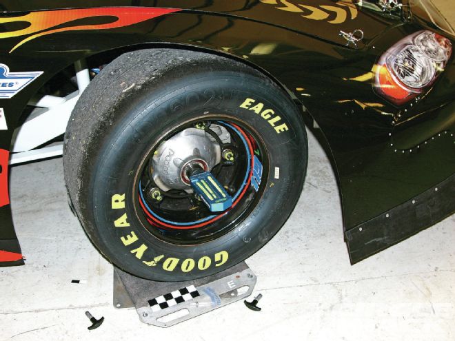
 One of the most basic and important settings on a race car is caster and camber. These two conditions affect the drivers feel when steering the car through the turns, as well as the amount of footprint the tire will ultimately have.
It's important to know how to properly measure for the amount of caster and camber in your race car. All teams need to learn the proper procedure for determining the amount of each that exists in the front end geometry of their cars.
Caster and camber settings are set relative to the type of car and the design of the racetrack. When you determine the correct settings for each, you need to maintain those settings. We will discuss what affects the caster and camber in our race cars, as well as how to properly measure them.
Caster Defined
Caster is a design condition that, in addition to the spindle king pin angle, serves to cause a wheel to want to track straight ahead. A common example is a bicycle front wheel and fork assembly. The tube that the handlebars are mounted to is mounted in a set of bearings above the fork and from a side view, this tube is angled so that the bottom bearing is ahead of the top bearing. If we turn the front wheel away from the direction of travel, it will want to return to straight ahead by the effect of caster. The same effect is present in the front wheel assemblies of our race car.
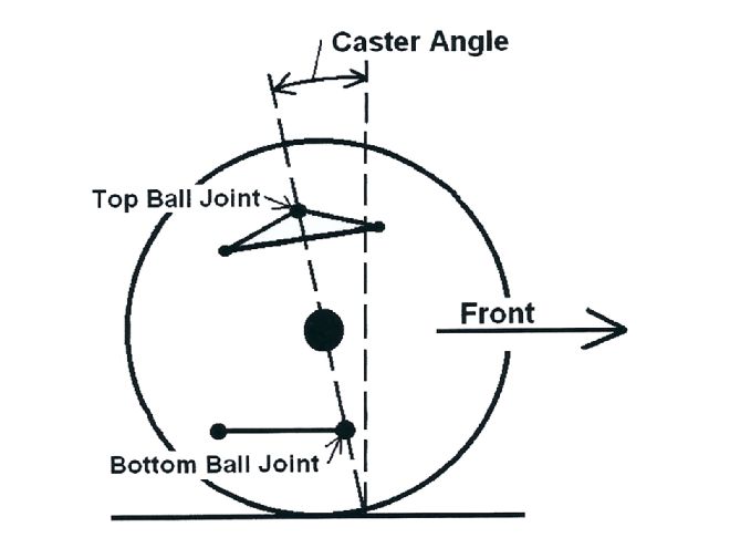 1. Positive caster in the front wheel assembly is created when the ball joints are offset, from a side view, so that the upper ball joint is farther to the rear of the car than the bottom ball joint. The degree of caster is related to the angle in degrees that a line through the ball joints forms from a vertical line.
What Caster Does
To ease the amount of effort it takes to turn the wheel left in our circle track race cars, we introduce caster split into the design. Split means that we set different caster amounts into each wheel assembly so that the car will naturally want to turn to the left and thereby reduce the amount of effort it takes for the driver to hold the steering wheel when negotiating the turns.
Proper split for asphalt circle track racing means that the left front wheel will have less positive caster than the right front wheel. In some cases, teams have been known to set negative caster in the LF wheel and positive caster in the RF wheel.
For dirt racing, equal caster to minimum amounts of caster split are proper due to the fact that the wheels will be turned both ways as the car enters (left), corrects for rearend slide (right), and exits the turns (back to the left). So, the steering wheel must be more equal in steering effort for left and right turning for a dirt car.
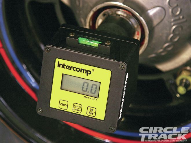
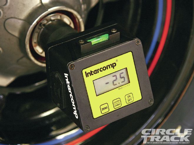
To measure caster in each wheel, we use a caster/camber gauge. This tool attaches to the wheel hub. To check the amount of caster, we need to follow these instructions:
 2. To begine checking caster set the bubble at zero on the caster side of the gauge. Some teams use one edge of the bubble so that reading the angle is more accurate than trying to estimate the center of the bubble.
Adjusting caster
To adjust the amount of caster in each wheel, you will need to move the upper ball joints fore or aft. In rare cases, you can also move the lower ball joint. Just reverse the following instructions when moving the lower ball joint. To increase the amount of positive caster, move the top ball joint toward the rear of the car. Some cars have slots cut into the upper chassis mounts for this purpose.
 3. For a digital gauge, turn the wheels to the right so that they turn 20 degrees from straight ahead. Level the gauge and then push the “zero” button to set zero in the display.
If you have permanently attached vertical mounting plates that the upper control arms are attached to and do not have slots, then you can vary the amount of shim spacing for each of the bolts that attach the control arm to the chassis to move the ball joint. Wider spacing at the front bolt (control arm shaft inside of the mounting plate) will move the upper ball joint to the front creating less caster at that wheel and so on. This is not the preferred method though.
Once you have established the exact caster amounts for each wheel using the above method, (if not using slotted control arm shafts) you should order an upper control arm that has the ball joint offset to give the correct amount of caster at each wheel. That way, you can use the same shim spacing for each mounting bolt to connect the upper control arm shaft to the chassis.
How Much Caster Split?
Normal caster splits for most short track asphalt applications are around 2 to 4 degrees of difference. The LF caster might be 1-2 degrees and the RF caster might be 3-5 degrees. The higher the banking angle of the racetrack, the less caster that is needed because less steering effort is needed due to the banking. Also, the tighter the turn radius, the more caster split is needed. Driver preference plays a big part in getting the caster split right for your application.
 4. Turn the wheel past straight ahead on the turn plates and go past that to 20 degrees left turn. Re-level the gauge and read the amount of caster in the RF wheel. Repeat for the left front wheel as we have outlined.
If you decide to run negative caster at the LF (meaning the upper ball joint is ahead of the lower ball joint), the split will remain the same to achieve the right amount of turning assist.
Camber Defined
Camber is when a wheel is tilted so that the top of the tire is either closer to the centerline of the car or further from it than the bottom of the tire. Negative camber is when the top of the tire is closer to the center of the car than the bottom. Positive camber is when the opposite exists, the top of the tire is farther away from the center of the car than the bottom of the tire.
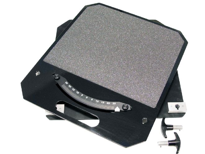
5. It is a good idea to use turn plates in order to know exactly when you have turned the wheel 20 degrees, the standard amount for caster measurements according to SAE standards, which most gauges are calibrated to. To use any other amount of steering will yield the wrong numbers for caster.
In circle track racing, turning left we use positive camber on the LF wheel of the car and negative camber on the RF wheel. We can easily check the amount of camber by using a caster/camber gauge and reading the amount directly on the camber bubble vial or the readout on a digital gauge.
We have learned some interesting and important aspects of tire camber for short track racing over the years. We have always known that a racing tire will flex under the stress of cornering and the tread will move and roll under the wheel when the extreme forces associated with cornering are present. Different brands of tires have different stiffness of sidewall construction and therefore roll over more or less.
Tire temperatures tell us more about how much static camber we need than anything else. The overall goal is that we need the tire contact patch to be relatively flat on the racing surface at mid-turn in order for the tire to be able to provide the maximum amount of traction it is capable of giving. This is often referred to as the maximum “footprint.”
Tire temperatures can alert us to improperly set static cambers. A front tire that is hotter on the inside edge (side toward the inside of the racetrack) usually has too much positive camber in the case of a LF wheel, or too much negative camber if it is the RF wheel.
Camber Change
The cambers will change as the car dives and rolls as it enters and negotiates a turn. True camber change is a combination of both chassis dive and chassis roll. Gone are the days when we would jack up the wheel and measure how many degrees the camber changed in each inch of bump. Those numbers really don't tell us anything. That is only part of the answer. Chassis roll has an affect that adds or subtracts from what dive does. So, what we really need to know is what the dynamic camber ends up at after the car dives and rolls, just like it does in the turns.
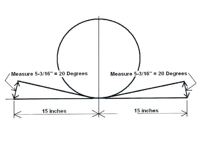 6. If you don't have turn plates, you can measure on the floor to get exactly twenty degrees of steering, cut a 30-inch piece of 1X6 wood or similar straight, flat piece and lay it against the tire. Mark midway on the wood (15 inches) and line that up with the hub. Mark the floor at the outside corner of each end of the wood. Turn the steering wheel until the ends have moved 53/16 inches and you will have turned the wheel 20 degrees.
The left front always loses a lot of camber, so we need to allow for that in setting the amount of static camber. Generally, if we end up with between 1/2 to 1 degree of positive camber at the LF wheel after the car dives and rolls, then that tire will have the dynamic camber that it needs.
The RF camber change is a little different. We can design our car so that the RF camber doesn't change after dive and roll with the more conventional setups. This is actually exactly what that tire wants for most short track applications. The reason for this is that as we enter the turn, the RF tire takes a set fairly quickly. If the camber continues to change after that initial set, then the tire will give up traction and the car will usually push.
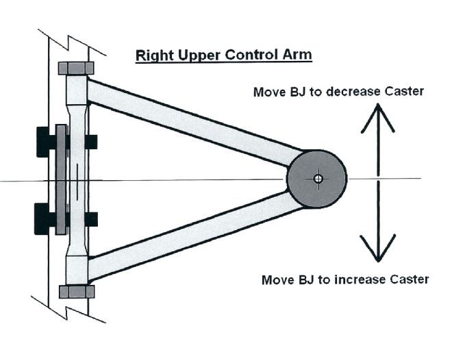 7. Move camber adjustment shims back and forth from each mounting bolt, or slide the control arm shaft if it is slotted, to adjust the amount of caster in each wheel. This will move the upper ball joint forward (to reduce caster) or to the rear (to add caster).
The more modern soft spring setups where we run on bump stops will do basically what the conventional setups have done in years past. Once the car is on the bumps, the cambers are basically fixed and don't change much around the entire racetrack. That lack of change is one of the positive aspects of the soft spring setups that we have seen.
Still, with any setup, the cambers will change from where they are at normal, static ride height. The right upper control arm angle mostly controls the amount of RF camber change, so we try to work with that control arm angle and once we have the minimum amount of camber change, we leave that angle alone as we further design our front end for Moment Center location.
Spindle Height
Spindle height affects the amount of camber change at each wheel too. The taller the spindle, the less camber change will occur. Trends that have taken place in the past have resulted in greater camber change due to the use of shorter spindles. That trend is in the reverse mode now as car builders move toward using taller spindles.
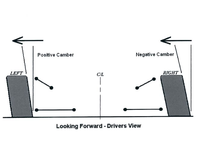 8. From a driver's view, the positive left front camber causes the top of that tire to lean out away from the centerline of the car. The opposite is true of the RF tire, which has negative camber. On that wheel, the top of the tire leans in toward the centerline.
Measuring Camber Change
We can measure camber change by several different methods. In the shop, we can set the chassis ride heights just as they would be at mid-turn on the racetrack and then directly measure the camber at each wheel. To do this, we will need to know the shock travel at mid-turn, which is very hard to estimate.
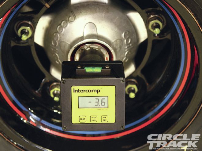 9. For measuring static camber, just read the amount on the vial for a manual gauge or the display on a digital gauge. Make sure the car is at ride height with all of the weight in the car including the driver. Air the tires up to operating pressures. These setting may change once the car is raced and the tire temperatures have been evaluated. To measure the cambers as they might be at mid-turn on the racetrack, lower the car to the attitude it would be at on the track. This position is a reflection of camber changes due to chassis dive and roll.
If we look at the shock travel indicators on the shaft of the shock, it always tells us total shock travel which includes braking, going over bumps, banking changes such as exiting the racetrack and driving down onto the apron (this could be quite a lot of LF shock travel at some high banked racetracks) or something as simple as steering the car back and forth to warm the tires before running hot laps.
Sometimes it is sufficient to place the car to where the front valance looks similar to what it is on the racetrack at mid-turn. The team can remove the springs, place spacers under the crossmember and adjust the height until the car looks the same and then measure the camber. When using bumpstops or bump rubbers, you can lower the car onto those and the attitude will be close to what happens on the track.
Conclusion
Remember that caster settings are mostly adjusted for driver preference and comfort and are relative to the design of the track, and camber settings are important so that the front end will have the maximum amount of footprint and traction to use to turn the car at mid-turn. Many of our problems related to a car that won't turn well come from incorrect camber settings and camber change problems.
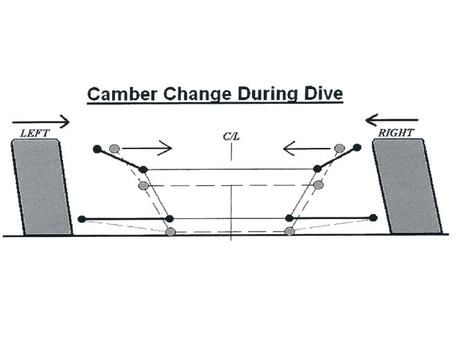 10. As the chassis dives, the upper ball joints are pulled in toward the centerline of the car. This causes a movement toward negative camber for both front wheels. The greater the angle of the upper control arms, the more the cambers will change from chassis dive. But this is not all that is happening. We also have chassis roll, even with the bumpstop setups.
Often, a car that has a serious push can be helped by analyzing and adjusting the static camber as well as knowing the camber change amounts. For dirt cars, taking tire temperatures may not be feasible, but measuring tire wear can have the same effect as temperatures. The more wear, probably the more temperature that part of the tire experiences. Even wear translates to more even tire temperatures and the best camber settings.
Gone are the days when we would jack up the wheel and measure how many degrees the camber changed in each inch of bump
Remember that caster settings are mostly adjusted for driver preference and comfort and are relative to the design of the track, and camber settings are important so that the front end will have the maximum amount of footprint and traction to use to turn the car at mid-turn
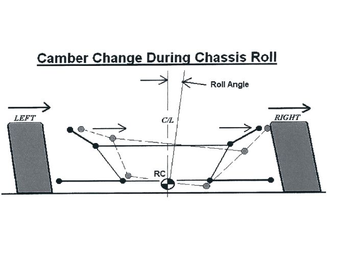 11. Besides chassis dive, when we turn the car left, the chassis also rolls, even when using bumpstops and large sway bars. As the chassis pick-up points move in roll, the upper ball joints move to the right. This causes the LF wheel to lose camber toward the negative and the RF wheel to move toward positive camber. If we combine the effects of dive and roll, we see where the LF wheel will lose in both dive and roll, whereas the RF dynamic camber will be a product of combining two movements that are in opposite directions. That is why we can achieve a net zero change in camber at the RF wheel with more conventional setups.