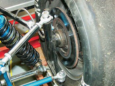
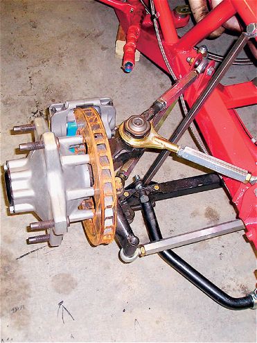
 Spindles come in all shapes and sizes. This 31/44-scale race car has spindles fabricated out of steel tubing and uses Heim joints for the ball joints. The ball joint heights are adjusted by spacing the Heim joints off the tubing.
We speak as often as we can about the moment center (MC) and its importance to the dynamics of the front of our race cars. It has been proven by countless racers on dirt and asphalt that this one invisible point can cause more headaches than most settings on the car. It is literally the center of the race car chassis universe.
The problem arises in knowing how to properly make changes that will move the MC to the desired location. Changes can be made in several different areas, or a combination of areas, to manipulate the location of the MC. Let's take a look at the various areas in which we can usually work and see exactly what we would need to do to affect our MC location. If for some reason you cannot work with any of these areas, work where you can, but try to move your MC to a position where it will do you the most good.
There are three main areas where we can work to change the arm angles. These are the chassis, the control arm lengths, and the spindle. The spindle may be easier to change than the chassis in most cases, especially when working on a stock clip car with rules that don't allow changes to the chassis mounts.
 The relationship of the upper and lower control arm angles produces an invisible point called a moment center. The position of the spindles and the chassis attachment points determine the angles. The location of these points is extremely important to the car's turning ability.
Spindle Design
Many times we're faced with incorrect arm angles because of a spindle that is either too short (usually) or too tall. If we can find a spindle with different dimensions, we may be closer to having the correct arm angles than if we move the chassis points. Besides, there are mechanical restrictions to moving certain chassis points, such as the lower chassis mounts.
In many cases, a car will have too little upper control arm angle and too much lower control arm angle. This is a result of having a spindle that is too short. Remember the spindle pin or hub is always in the same place vertically if we use the same tire circumference. We can change the height of the spindle so we can move the upper and/or lower ball joints to affect the arm angles.
If we change from a 731/44-inch-tall spindle with an offset of 311/42 inches from the bottom of the spindle to the center of the pin to an 811/42-inch-tall spindle with a 311/42-inch offset from the bottom to the pin center, then we have raised the upper ball joint by 31/44 inch and not changed the lower control arm angle.
We can install a 911/44-inch-tall spindle with a 411/42-inch offset from the bottom to the pin and gain 11/42 inch of height on the upper ball joint while lowering the bottom ball joint by 1 inch. This increases the upper control arm angle and also reduces the lower control arm angle.
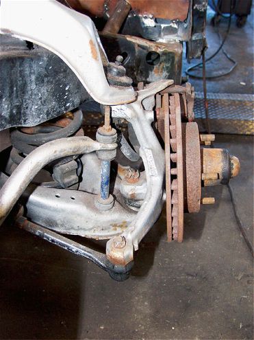 For stock applications, the upper control arm angle may well run uphill from the ball joint to the chassis. This is terrible for moment center design as well as for camber change. We need to lower the chassis mount and find a longer "stock" spindle to take this spindle's place.
The type of ball joint we use can affect the control arm angles. A standard K-6141 press-in lower ball joint is 31/48 inch shorter than a K-6117 press-in lower ball joint. Using the longer part reduces the lower control arm angle. There are also aftermarket ball joint manufacturers who offer different-length ball joints.
For years, Coleman Racing Products has offered a mono-ball replacement for the upper and lower ball joints. These units are adjustable in height by moving spacers above and below the mono-ball. Howe Racing Enterprises offers its precision ball joint replacements that are interchangeable with the upper and lower ball joints. You can order longer replacement studs for Howe's ball joint in plus lengths from +0.1 inch to +0.5 inch in 11/410-inch increments.
Spindle Quality Control
Another factor concerning spindles that goes unnoticed is in the way the builder of the spindle taps the tapered holes that the ball joint stud goes through. To date, we have not heard of anyone checking the depth of taper on each spindle. If this dimension is not kept consistent, each spindle may be of a different length between the centers of rotation of the upper and lower ball joints. You conceivably could install two 911/44-inch-tall spindles on your car and one might be longer, ball joint to ball joint, than the other
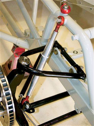
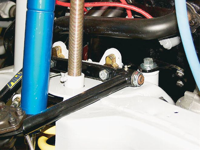 This is a Modified stock clip, upper control arm mount. This is one of the cleanest and most efficient designs. It utilizes an adjustable mounting plate and aftermarket one-piece upper control arms. If every promoter would allow such changes, the competition would improve along with the handling of the cars.
This unknown factor can wreak havoc on our frontend geometry settings, and we might not even know how it has happened. For example, I could go to a lot of effort to measure my car, make the necessary changes, and then go racing and have a lot of success. Then, the inevitable happens and I get pushed into the wall, bending my right-front spindle. No problem, I think, and order a new 911/44-inch spindle. If the ball joint-taper holes in this spindle were drilled 11/48 inch deeper than the previous spindle, I could end up with an entirely different MC location.
I ran the calculations on a sample car, an outlaw Late Model. The dynamic MC location (its position in the middle of the turns) with the current design is 2.449 inches high and 0.137 inch right of the centerline of the car. I lowered the upper ball joint by 11/48 inch and raised the lower ball joint by 11/48 inch. The MC ended up at 2.230 inches high and 2.288 inches left of centerline. I would need to lower the Panhard bar by 11/44 inch on both sides to maintain a balanced setup after installing that spindle. It could be worse.
If my taper holes are drilled 11/44 inch deeper for the upper and lower ball joint shafts, the MC moves to 1.079 inches high and 18.764 inches left of centerline. That's no place for the MC. My car's handling will go bad and I won't even know why. I will usually blame it on a possible bent clip or whatever else comes to mind.
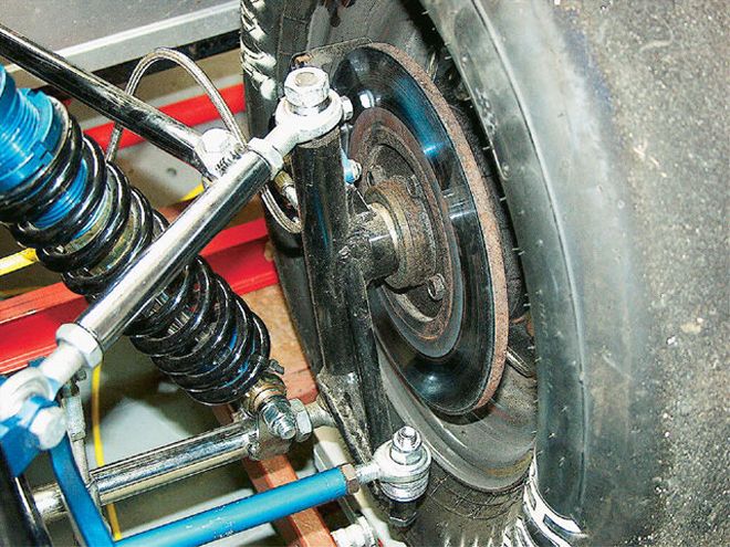
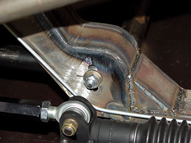
 Here is a clever idea we came across. This team drilled and tapped the spindle and welded a nut on the top and bottom. They then used a large machine head bolt through a mono-ball to create the ideal arm angle for their Late Model. This arrangement allows a much wider range of adjustment, especially for raising the pivot point.
It would be a good idea to keep track of your spindle's taper hole depth after you have measured your car for the MC location. Keep these dimensions in a book, preferably your setup book. If you need to change spindles for some reason, you can check the depth of the new spindle ball joint hole depths and compare those with the "standard" you have established.
Chassis Mounting Point Heights
The heights of your control arm inner chassis mounting points can also be changed to affect the location of the moment center. We are often limited in how far we can go to move these points. To locate the MC in the correct spot, we might need to make changes to the inner mounts and the spindle.
Many chassis manufacturers now build their cars with adjustable mounting points so that we can move the upper and/or lower mounting points up and down to change the arm angles. This comes in handy if we need to make small changes to the MC location to adjust for different racetrack designs.
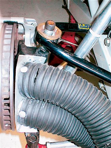
 Many Modified cars as well as some Late Model cars have a two-piece upper control arm. These have adjustable links for camber adjustment. The chassis mounting points have plenty of room for vertical adjustment. Please do not write in about the brake rotor being installed backwards. This team has already fixed that problem.
The track banking angle is directly correlated to the MC location. The lower the banking angle, the more toward the left we can position the MC. The range may be different for each type of car, but it is generally true that low banking requires a location more toward the left while high banking requires a location more toward the right.
The MC is usually designed for location as well as ideal camber change for the right-front wheel. We need to have zero camber change at the right-front wheel after the car dives and rolls in the turns. That is what the tire wants. The upper control arm angle largely dictates the camber change for the right-front wheel. Once we have established an upper angle at the right-front, then we need to keep that angle. Changes we make to move the MC right or left should be done by altering the upper-left arm angle. That's why we need adjustable upper mounting plates, especially on the left side.
Do not be afraid to cut off the upper mounting brackets and mount new ones that are of a correct height. It ends up being a few hours of work and months, or even years, worth of good results. Before you cut, make sure you know exactly where you need the new bracket to be placed both vertically and laterally so that the control arm shaft will clear the plate with the proper camber set.
 A chassis designed for moment center adjustability will have slotted upper control arm brackets as well as slots in the lower control arm mounts in the crossmember. The upper plate shown is designed to take different slugs with offset holes. By changing the slugs to a different offset, we can easily change the upper arm angle.
The lower control arm angles mostly control how far the MC moves from static location (at ride height and down the straightaway) to the dynamic location (at mid-turn). Excess lower arm angles cause the MC to move farther than we would like. If we can keep the lateral movement of the MC to less than 4 inches, the car will be more consistent.
Most cars are not designed with adjustable lower control arms. In many cases, we need to find ways to move the lower mounting points up to reduce the lateral movement of the MC. If there is enough room above the inner bushing assemblies, we can drill new holes to attach the lower arms. If there is not room, we can cut out the crossmember and weld a hat onto the upper portion to strengthen the support.
Anytime we cut and weld on the chassis, it's a lot of work. Failing to take the time and effort will result in an entire season of frustration and poor handling. It is much better in the long run to take our medicine early and enjoy a car that is faster and more consistent.
Historically, the chassis builders have frowned upon teams hacking up their cars. I always tell the teams that once you buy the car and roll it out of the builder's shop, it's yours to do with what you like. Do what you need to do and don't worry about what anyone thinks of what you're doing.
Nowadays, many of the top car builders on both the dirt and asphalt side of racing are paying a lot more attention to the moment center design on their cars.
Control Arm Lengths
We can usually change our control arm lengths to help make changes to the arm angles. This is the easiest way to manipulate the MC location. If we install a different length arm and retain the ball joint, spindle, and inner mounting heights, we will have changed the arm angle as well as the camber change characteristics.
There are limits to how far we can go in making length changes. We don't necessarily want an arm that is way too short or one that is excessively long. The length can be limited because of engine components and the actual upper mounting plate location.
Changing to a shorter upper control arm will add angle to the arm and affect a move of the MC in the direction of that arm. A shorter arm will cause a greater change in the camber from chassis roll and chassis dive. Installing a longer arm does just the opposite.
General Truths Here are a dozen basic truths about MC design and placement:1. The upper control arm angles, especially the upper-right arm angle, dictate the lateral location of the MC and the camber change characteristics.
2. The lower control arm angles control the amount of lateral movement from static location to dynamic location. Less angle (chassis mounts lower than the ball joint) equals less movement. More angle equals more lateral movement.
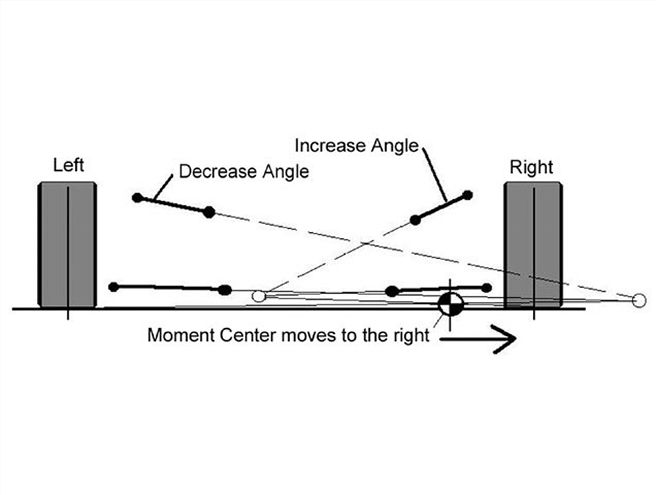
3. Taking angle out of the upper-left arm and/or putting more angle into the upper-right control arm moves the MC range to the right.
4. Putting more angle into the upper-left control arm and/or taking angle out of the upper-right control arm moves the MC range to the left.
5. Installing a longer control arm using the same mounting holes and ball joint/spindle combination will reduce the arm angle.
6. Installing a shorter control arm using the same mounting holes and ball joint/spindle combination will increase the arm angle.
7. Higher-banked tracks require an MC range that is more to the right of the centerline of the car.
8. Lower-banked tracks require an MC range that is closer to the centerline of the car, or even left of the centerline in the case of a dirt car.
9. Very high-banked tracks require less upper control arm angles to control camber change. This compensates for the excess vertical movement from the high amount of mechanical downforce in the turns.
10. Low-banked tracks require more upper control arm angle to help control camber that results from chassis roll.
11. Softer springs require an MC location that is farther to the right.
12. Stiffer springs require an MC location that is farther to the left.
Conclusion The most important thing to remember is to take the trouble to measure your car and know where your MC is located. If changes are needed, go ahead and make those changes, doing whatever it takes to move the ball joints or chassis mounting points. You, and you alone, are responsible for how your chassis works. The effort you put into this area will pay you back many times over.