 Taking time to align your car is worth every minute and ounce of effort. Knowing where your car is pointed and eliminating any errors can save countless hours of frustration and a lot of wasted expense chasing an errant setup. Many handling problems can be traced directly to misalignment of the suspension.
We always try to think of the elements of a good, winning setup in terms of priority. It saves time and energy to put the most important items at the top of the list and work on them first. In Circle Track, we stress the importance of moment center design and having a balanced setup to give the car what it wants. Before this can be accomplished, you must address the critical area of chassis tuning.
We have talked about the importance of proper steering related to Ackermann as well as the alignment of the rearend. Now, we will show how to align all the critical parts so the wheels will track true to the path of the race car. Poor alignment can ruin an otherwise great setup.
A good, well-balanced setup is a product of making sure all of the elements are in place. Many times I have run across a car that has all the right ingredients of roll center design-a good balance of front and rear suspension design, and proper weight distribution. It has all the necessary components, except for one thing-it has a serious alignment problem.
Whole-car alignment is critical. Four-wheel alignment can be the final setup parameter that can take you to the front or keep you in the rear of the field. The problem is that no amount of manipulating other setup components will overcome a wheel-alignment problem. While it is probably true that a car out of alignment is more forgiving on dirt, it is important on both dirt and asphalt to have your wheels properly aligned.
 In this example, the rearend is pointed to the right of the centerline of the car. This will help free up a tight car, but it will produce a severely loose condition under throttle application. The loss of bite off the corner will hurt the lap times more so than what might be gained from freeing the car up.
1. Toe Settings - Proper toe settings at the front and the rear are important. A set of tires not toed correctly will create a lot of drag, much like applying the brakes.
2. Rear Alignment - The direction that the rearend is pointed in relation to the chassis can dictate how a car will behave in the turns. For example, on turn entry, if the rearend is pointed to the right of the chassis centerline, no amount of setup tuning will prevent the car from being loose. That looseness will stay with the car throughout the turns, especially ruining the turn exit. If the rearend is pointed to the left of the centerline of the chassis, the car will be tight through the middle and off the corner.
3. Front to Rear Tracking - The tire contact patches must track straight ahead from front to rear. In most cases, you need to line up the right-side tire contact patches. The final alignment will show the right-side patches are in line with one another along with the rearend being perpendicular to that line.
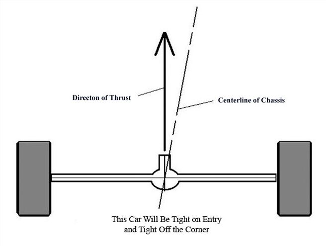 Here the rearend is aligned so that it is pointed to the left of the centerline of the chassis. This makes for a tight-handling car and, in most cases, the driver cannot steer against the tendency for the rear of the car to pass the front on the left side.
4. Ackermann Adjusted - The last alignment priority is making sure you have very little Ackermann, which is the creation of additional front toe as the wheels are turned. On most quarter- to half-mile racetracks, little Ackermann is needed to make sure the wheels are tracking inline with the radius of the turn for each wheel. Calculations show that for those tracks with fairly large radii (much more than was used to design for passenger cars for turning the corner at the stop sign), a small amount of added toe is needed to properly align the front wheels to their individual radii.
There used to be only one reliable way to align a race car. You used a string. You either measured to the tires at hub height or measured at the floor by creating right triangles on the floor. That's still a viable way to do it-and necessary for lower-budget race teams.
A quicker and more accurate way to align the car in all areas is by the use of a laser system. The key to maintaining accuracy in a laser system is to be able to check the tool to make sure the beam is truly tracking at right angles to the mounting device. The unit we used is called a True Laser Track. The laser can be removed from the hub adapter and turned to check if the laser pointed to the same spot on a target. This must be done each and every time we use the tool to check alignment.
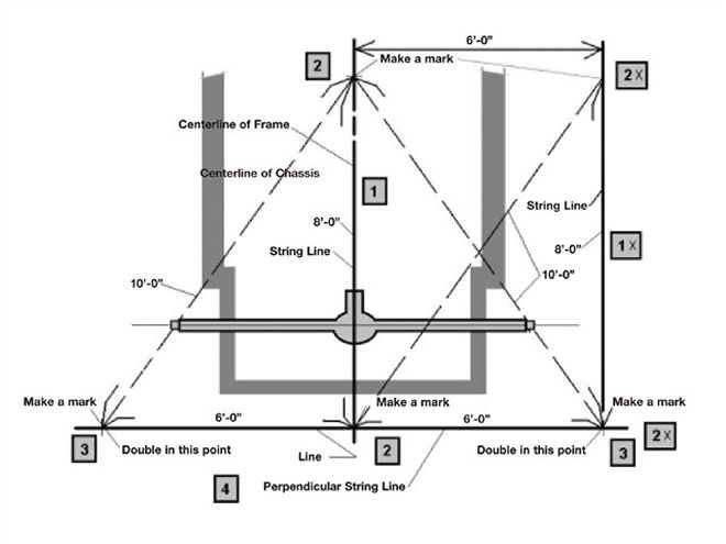
In the past, it was common to string a car by making marks on the floor. This is a good method for checking rearend square and can be used to line up the right side tires. It is a little slower to do than the raised string method but can be more accurate due to the process of dropping points down to the floor with a plumb bob and then making direct measurements to the rearend. Neither string method will show you Ackermann amounts.
The laser system is one that attaches to the wheel hubs (models for both Wide 5 and 5-on-5 hubs) and can be rotated 360 degrees, and leveled both horizontally and vertically. The laser uses targets at each end of the car. For the analog (string) method, the nylon string we used was from the local hardware store.
We will go through the process using both methods in order to show you how to perform each step.
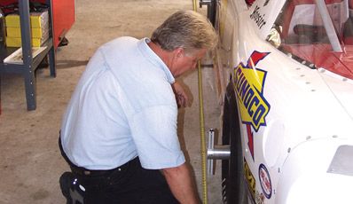
Step 1 - Check both the front wheels and the rear wheels for runout. This means as the wheel rotates, the outer edge of the tire will wobble slightly. You must compensate for this slight distortion by finding the extreme high spot at a point equal in height to the hub height. Use a jackstand to hold the tape steady and rotate the tire, noting the distance from the stand. Upon locating the high point, mark it with an arrow and then rotate the tire (front or rear) so the arrow is at the top pointing straight up.
Now, check the toe at the rearend. Use toe plates for the analog method. Even small amounts of toe are not acceptable. Be careful how each person holds the plates. Do the measurement several times to ensure accuracy.
If using the laser system, thoroughly clean the surface of the hubs and make sure there are no protruding threads from the bolt holes. It is recommended you go over the hub surface with a flat file to eliminate any bulges or edges of metal that would cause the laser to be improperly aligned. Attach the laser to the rear hubs.
Set four targets, two on each side, at equal distances forward and rearward from the vertical center of the rear hubs. Center the laser beam on each target and measure the distance between the centers at the front and also at the rear. If these widths are not the same, the rearend is toed and must be straightened before continuing.
 We used a highly accurate coordinate geometry software program to calculate the exact amount of Ackermann-or steering angle difference-between the two front tires needed for quarter- and half-mile racetracks. We then translated the angles into inches of toe. For a half-mile track, we would need only about 1/64 inch (or 0.03 degrees) of additional toe so the tire would follow the needed track due to the difference in radius between the front wheels. For a "tight" quarter-mile track, we need slightly more toe gain, or about 1/16 inch (or 0.11 degrees) of additional toe. These numbers represent fractions of degrees of Ackermann, not whole degrees. Remember, each 1 degree of Ackermann is 1/2 inch of toe.
Step 2 - Once the rearend has been toed straight ahead, shine the right rear (RR) laser so that you can measure the offset to a straight framerail at the front and rear or two places offset from the centerline of the chassis. Most car builders will align at least one framerail parallel to the intended centerline of the chassis. It may be located on the right side or at the weight box on the left side next to the driver. Adjust the rearend so that each measurement to the frame is equal. This means the rearend is perpendicular to the framerail and hopefully the intended centerline of the chassis and the installed body.
This measurement can also be done with a string by using a square to come down to the floor, then measuring over to the frame or centerline of the chassis to align the string with the framerail. You can measure over to the tire to check the rearend alignment in relation to the framerail. Equal measurements to the tire front and rear means the rearend is perpendicular to the chassis centerline.
Step 3 - Center the front steering rack. This is done by turning the steering wheel lock to lock, then back half the number of turns from full lock in either direction. Once midrack (or midbox with drag-link steering) is found, lock the steering column with two vise-grip-type pliers. With the lasers attached to the front hubs, level the front lasers (vertically) and reposition the targets so that they are equal distance from the center of the front hubs. We used 14 feet as a convenient distance that would clear the rear of the car, while not extending too far to the front if the space were limited in the garage. Remove the front lasers from the holders and align the centers of the four targets with the beams from the rear lasers.
Reattach the front lasers and rotate the right front laser so that it shines on each target. Note where it is positioned in relation to the centerline. If the point where the beam strikes each right side target is not an equal distance from the target center as well as on the same side, adjust the length of the right side tie rod to align the right front wheel parallel to the rear wheel. The points do not need to be exactly on the target centerline, only equal distance from the centerlines.
With the string, simply measure to each side of the tire with the tape and make both measurements equal by adjusting the tie-rod length.
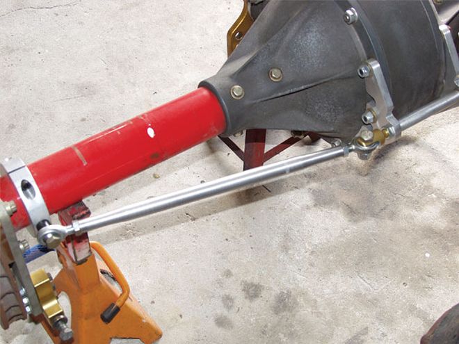 This handy tool produced by FinishLine makes adjusting rearend toe fast and easy. The tie rods-one on each side-can be widened or narrowed, which moves each wheel in or out. Rearend toe adjustments can be made at the racetrack in minutes.
Step 4 - Once the right front (RF) wheel has been adjusted to point straight ahead parallel to the RR hub, level the RF laser (vertically) to shine the point on the floor. Rotate the RR laser so that its point shines next to the front laser point on the floor. This shows the alignment, side to side, of the tire contact patches, the beams being equal offset distances from the centers of the contact patches. Adjust the Panhard or J-bar length so that the right-side laser beams (tire contact patches) are one point. This means both right side tires are lined up.
As you adjust the rearend side to side, there is a possibility that the alignment will change as the rearend moves laterally. You must recheck to make sure the rearend is still perpendicular to the framerail each time you adjust it. This may take several tries to get both the rearend square and the right-side tire contract patches lined up.
When using the string, you must compensate for the camber of the right front wheel which moves that tire contact patch out. At the hub height, if you line up the tire sidewalls, the RF tire contact patch will be outside that line due to the negative camber present in the RF wheel. Look at the chart to estimate how much to compensate for the camber. Subtract the compensation amount from the offset read at the RF wheel to find how far from the string the RR wheel needs to be in order to line up the right side tire contact patches.
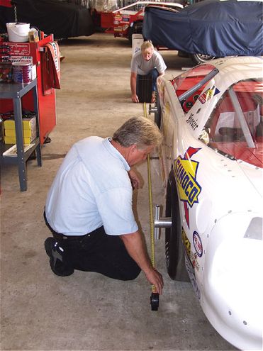
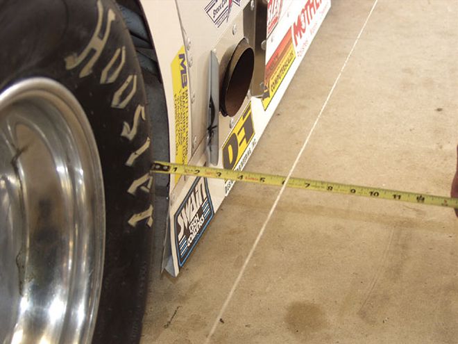 When using the string method, set the string height at hub height and align the string with the framerail. Measure to the tire bulge at the front and rear to make sure the rearend is square to the chassis. Adjust the trailing arm lengths to make the rearend perpendicular to the framerail. Once the runout is eliminated from the wheel in Step 1, this method becomes fairly accurate. Be sure to place the tape measure against the tire sidewall, away from any raised lettering.
Step 5 - It's time to set the static toe at the front wheels. You can use toe plates to do this. Remember to be careful and accurate and do the measurements several times to be sure of the numbers. Adjust the left-side tie rod to set your toe. Leave the right side alone.
Using the laser, at the left front (LF) hub, align the left-side targets with the LF laser at the front and rear and at 14 feet (168 inches) from the LF hub center. Measure the distance between the front targets and then between the rear targets. The difference in distance will reveal the amount of toe present in the front wheels.
To get the exact toe amount at the tire, first divide the front-to-rear difference by the distance between the targets (front-to-rear) of 336 (two times the 168 inches). This is the toe amount that exists in one inch. Then, multiply this number by the diameter of the tire (tire circumference divided by Pi or 3.1416). On an 85-inch tire, this diameter is 27.05 inches. Multiply the toe-per-inch by the tire diameter and you have the amount of toe in the front end.
Adjust the toe settings so that you have the desired amount of static toe in the front end. If you started out with the LF wheel straight ahead, dialing in 1/8 inch of toe at the tire will require about 3/4 inch of movement of the laser point at the front target. If you adjust your left side tie rod so that the difference in distance between the front and rear targets is 1 1/2 inches, you will have 1/8 inch of toe.
Step 6 - It is now time to measure for the amount of Ackermann present in the steering system. This can only be done accurately with the laser system. The analog method would have you use toe plates with degrees marked on them. These plates, as you will soon see, are not accurate enough for this measurement.
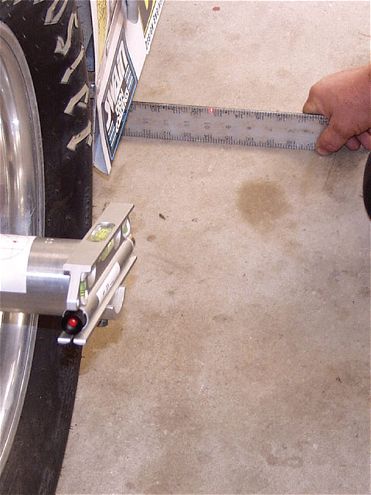 Make sure the laser or string line is parallel to the framerail.
With both front lasers pointed ahead, line up both targets so that the points are exactly on the centerlines. Turn the wheel the approximate amount that the driver does when negotiating the turns at the racetrack. Take the rear targets and place them 14 feet in front of the front hubs, and line up the centerlines with the laser points.
Measure between the two target centerlines on each side. The difference in distance between pairs of targets is now divided by 168 and multiplied by the tire diameter to find the Ackermann toe that is added to the static toe settings. The number should be low, around 1/64 inch of added toe for a half-mile track. This would be around 3/32 inch difference in the amount that each wheel turned (LF turning more than the RF), measured on the targets or 0.097 in decimal inches.
For a tight, quarter-mile track, the added toe due to Ackermann effect should be about 1/16 inch, or about 3/8 inch difference at the targets. Toe plates that might slip slightly cannot come near the amount of accuracy required when dealing with fractions of a degree.
This entire process should take only about an hour or two if there are several team members helping. That is little effort expended to make sure your car will track correctly and that misalignment will not interfere with performance. Repeat this entire process often, especially after kissing the wall or being involved in a crash. Once you're convinced your car is aligned, you can concentrate on the other important aspects of your chassis setup.
(Special thanks to Mike and Kristal Loescher)