Editor's Note: The material for this story was provided by Steve Smith, whose book Building the Mustang Ministock addresses the issues of the MacPherson strut suspension. Information about the complete work is available at the end of the story.
The law of supply and demand can play a critical role in a racer's life. Mini- Stock racers are finding this rule to be a hard reality. The supply of once popular models for race cars has diminished. Racers are looking for different options. One of the options gaining popularity is the '79-'93 Ford Mustang.
 The MacPherson strut system used in the 1979 and up Mustang is different. The coil spring is located on top of the lower control arm instead of being part of the strut unit.
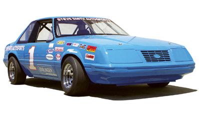
Popularly known in the Ford world as the "Fox-bodied Mustang," these cars, on the surface, appear to be likely candidates for the Saturday night Mini-Stock wars. However, there is one drawback that has caused some to shy away from this option: The car is built on a suspension platform that is different. It uses a MacPherson strut front suspension and incorporates a splayed four-link rear that can be susceptible to binding.
With a little knowledge of the general principles and application of acceptable theory, these suspension hurdles are quickly overcome. Steve Smith Autosports, with the help of Gary Ebeling and Esslinger Engineering, saw the challenge of creating a competitive Mini-Stock on this platform. Their finished product was competitive right off the trailer. They've also graciously agreed to share some of the tips used in building this car, an '84 Mustang.
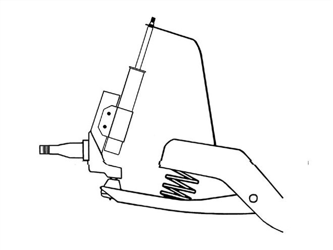
 Camber/caster plates replace the stock upper mounting hardware on the top of the strut tower.
The main problem with a MacPherson strut suspension is its tendency to gain positive camber at the outside front wheel as the wheel moves in compression and is steered. In building this car, the first chore was to reduce the positive camber gain and to set enough static negative camber to overcome the tendency.
A true MacPherson strut combines the shock absorber, spring, and upper control arm into one unit. The bottom of the strut is bolted onto a steering knuckle or spindle. The top of the unit bolts into a strut tower, built into the car's inner fender.
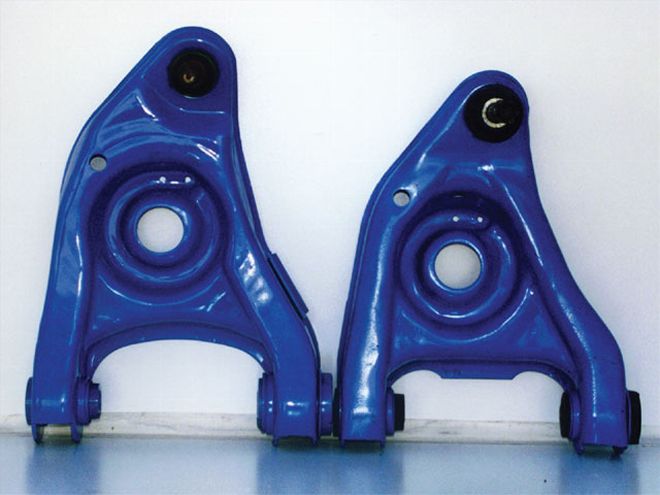 An '89 Mustang control arm (left) was used on this car. It is an inch longer than the stock arm (right) and will help get more right-front negative camber.
This design is not found in the Ford Mustang. The coil spring is not part of the unit, but instead placed between a lower control arm and a bolt-in frame crossmember. The spindle is attached to the lower control arm with a ball joint. The strut itself bolts to the top of the spindle.
In a strut suspension, the upper mounting point of the strut moves outward as the chassis rolls to the outside during cornering. At the same time, the inner mounting point on the lower control arm is pulled inward, creating positive camber, meaning a need for static negative camber. One way to create negative camber is by moving the inner mounting point of the lower control arm higher on the chassis. But this is not legal in most Mini Stock classes. A more practical approach is to use a longer lower control arm at the right front.
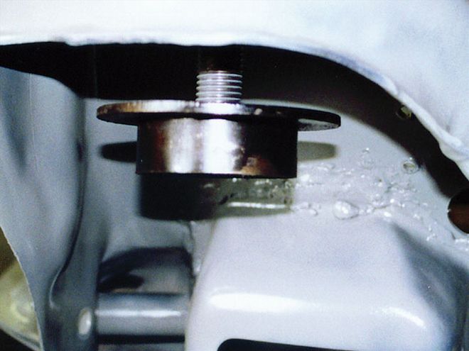
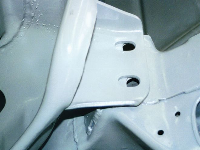 Slotted holes in the front suspension crossmember were elongated. This piece was set ahead 3/16 inch to build in additional positive caster.
Positive camber at the right-front corner of the car will make the car push because the tread face of the tire is losing contact and reducing grip potential. The right-front tire develops its maximum grip during cornering when there is 1.0 to 1.5 degrees of negative camber. In order to achieve this, there must be higher amounts of static negative camber to start. With Mustang strut cars, the range is 6.0 to 8.0 degrees negative.
To set large degrees of negative camber, you need to use some caster/camber plates at the top of the strut tower. A longer right-front lower control arm will be beneficial. In the case of the '84 Mustang, a newer model ('89) control arm was used, which was about an inch longer. The longer control arm moves the lower mounting point of the strut outward 1 inch, which adds negative camber. The longer control arm also creates a wider swing arc, which reduces camber loss in bump travel. With the large amount of static negative camber, the car will push on corner entry.
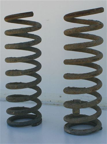 The stock springs that came from the car had a free height of 14 1/2 inches and were rated at 320 pounds.
Top of the Assembly Caster/camber plates replace the stock mounting hardware on top of the strut tower. Slots in the plates allow for plenty of adjustment capability. The right-front plate is wider to allow for the strut to be offset for greater negative camber. Since the top of the strut needs to pivot, racing plates use spherical bearings to reduce deflection of this pivot point. A large amount of positive caster helps reach the goal of static negative camber. Positive caster provides the self-centering effect for steering, but the more caster, the harder the driver's steering effort in the turns.
Slotted holes in the front suspension crossmember were enlarged on the project car, setting it ahead 3/16 inch when the subframe was reattached. It was done to create additional positive caster. Since it added caster on both sides, an adjustment to the left-side caster/camber plate could take the additional caster out of the left side.
The bolt-in subframe was stitch-welded to the framerails for additional strength. This method has a greater advantage than one continuous bead weld.
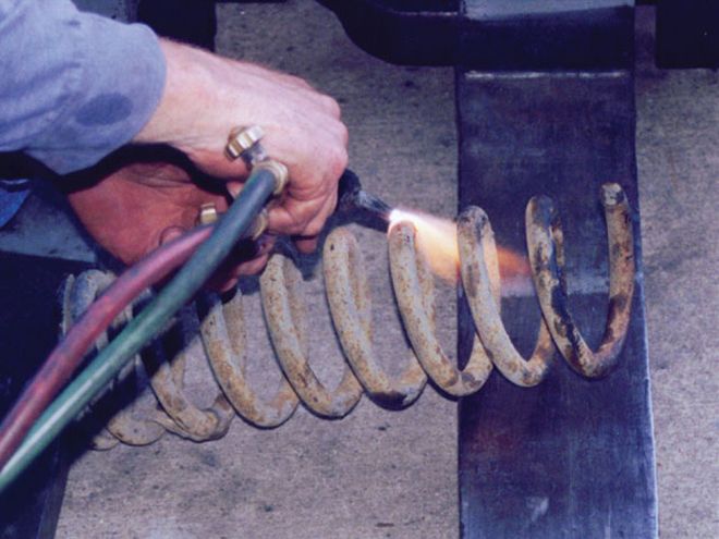 To lower the free height to the desired 9 inches, there were three coils cut from the springs. By cutting these springs, the rate was increased from 320 pounds to 500 pounds.
Mini-Stock racers can be faced with a challenge in the area of front coil springs, especially in spring height and rate. A stock spring on the '84 Mustang is 14 1/2-inches high and rated between 320 and 350 pounds. A racing spring will be 5 inches shorter and rated at 450 to 650 pounds. For those on a budget, cutting a stock spring could be an option, but you will need to understand the impact on the spring rate in doing this. To achieve this figure, divide the desired height by the spring's current height, which will give you a number less than one. Invert that number (divide one by the new number) and multiply the old spring rate by this new number to find the spring rate of the cut spring. A general rule of thumb to keep in mind is cutting one coil increases rate by 50 pounds.
Racing springs are linear, meaning each inch of compression takes the same amount to compress. Variable rate springs should not be used for racing applications if you are looking for the best route to a consistent setup. Variable rate springs have different spacing between coils.
 This is a side view of the adjustable spacer. The hat threads up and down on the all-thread bar.
The free height of a spring (with no compression) should be measured and noted. Periodically, the height should be checked by taking the spring out and measuring it again. A spring checker can help determine the consistency of the rate.
As a safety reminder, springs in a stock passenger car can be compressed several inches when installed. To properly and safely remove the lower A-arm and spring, use a spring compression tool.
Many racing associations will allow the use of aftermarket springs, so this car will be running on Hypercoil springs. Since weight-jacking bolts cannot be used, a coil spring spacer is employed. Spacers are available in adjustable and non-adjustable. The project car uses an adjustable spring spacer.
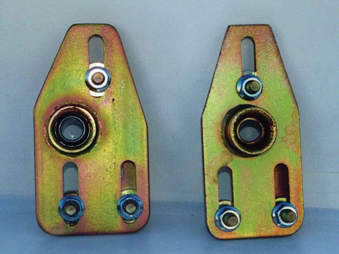
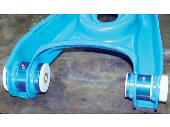 The rubber bushings in the stock application are not sufficient for racing. Polyurethane replacements are one option, but Global West has Del-A-lum bushings, which also work well for racing.
Traditional thinking about the front roll center is not applicable with a MacPherson strut suspension. Because of its use, a lower front roll center is not a goal of the MacPherson strut package. A lower roll center creates positive camber at the right front during cornering. There is nothing that can be done, especially in a stock-type class, to move the roll center location of a strut car. The only viable option is to adjust the suspension with the idea of countering the positive camber gain during cornering.
To find the roll center, make a scale drawing of the front view of the front suspension. A 1/4-scale drawing is a good choice. Draw a 90-degree line perpendicular to the top pivot point of the right-front strut. Extend that line until it intersects a line extending through the two pivot points of the right-front lower control arm. This intersection is the instant center (IC). Draw a line from the IC back to the right-front tire centerline to find the swing-arm length. Repeat the process for the left side. The intersection of the swing arms is the true roll center.
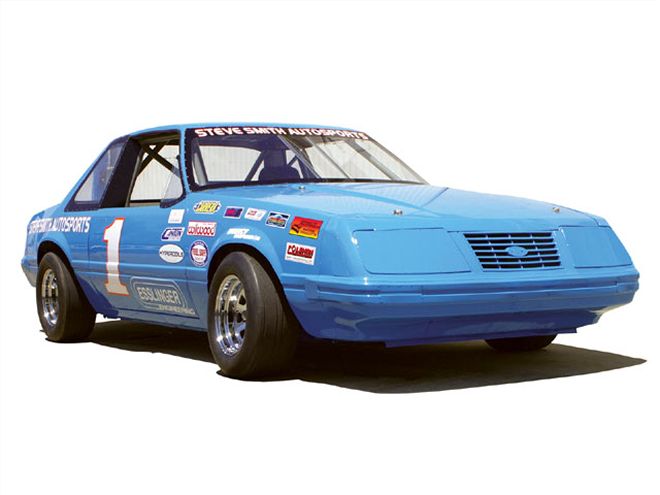
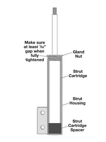 An inner view of a strut assembly.
Passenger cars come with rubber bushings in the upper and lower A-arms. These were designed to reduce road noise and vibration. This is not a concern with a race car since the stock rubber bushings flex and compress during braking and cornering. A stiffer material is needed. Global West Suspension Systems has a "Del-A-lum" product for lower control arms that was used on this car. The bushings are a six-piece design with an aluminum housing and an inner liner. The bushings have six bearing surfaces and a circular grease channel for efficient lubrication.
Another material choice for bearings is polyurethane. This is available in various degrees of hardness and you will need to know which hardness would best suit your application.
If your rules require rubber bushings, make sure to replace them with new parts before starting competition. When stock bushings are used, they should be checked every week for signs of wear and cracking.
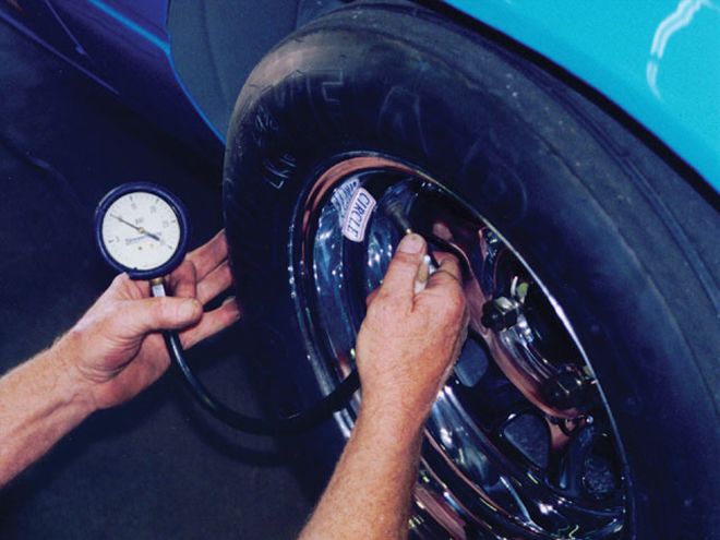 Before hitting the track, the tire pressure was checked. With rain approaching on test day, it was a good thing that the car was well prepared at the shop.
The project car was built with Carrera front struts, comprised of the housing and strut cartridge. The cartridge works along the lines of a racing valved shock absorber. In this case, the housing was shorter than a stock housing and could have been made shorter by cutting the tube.
Bumpsteer is the change in the steering angle of the front wheels during suspension travel. On the Mustang, one item for consideration was the change in the lower control arm. If the longer right front is used, the right-front tie rod from the same application must also be used. After checking bumpsteer, this car was found to have a straight line of toeing-in with bump travel and toeing-out in rebound. The condition was traced to the outer tie rod end being too high and/or the inner pivot point on the steering rack being too low. To combat it, the steering rack was raised with offset rack mounting bushings. This was done after ensuring enough clearance between the top of the rack and the oil pan. The use of taller tie- rod ends from the '90-'93 Mustang moved the tie rod lower.
Building the Mustang Ministock is available from Steve Smith Autosports Publications. The 136-page book provides the step-by-step creation of this car."> The book <i>Building the Mustang Ministock</i> is available from Steve Smith Autosports Publications. The 136-page book provides the step-by-step creation of this car.
Upon completion, the Mustang was taken to Irwindale (CA) Speedway for a test at the 1/3-mile oval. Like all track tests, the success rate would be contingent upon the amount of homework done. Having the proper setup at the shop saves time and effort when you hit the track.
In the first testing of the Mini- Stock, the car was fast. Fabricator Gary Ebeling also served as the test driver. In his career, Ebeling has logged nearly a dozen driving championships and more than 200 main event wins.
After taking a few laps to get familiar with the car, Ebeling was able to put it through its paces. With only one adjustment, the car was within three-tenths of the track record. Future track tests, with fine-tuning adjustments for this particular car, are expected to close the gap between lap times and the existing track record.
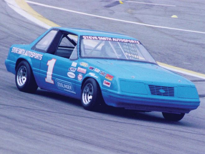 The project car gets on track. In its first test, it was well within striking distance of the track record at California's Irwindale Speedway.
The Mustang's MacPherson strut front suspension proved to be a challenge that can be overcome with a little effort. The unfamiliar system at the front and the rear stock four-link can be utilized to create a competitive car. This car also utilized a powerful Ford 2300 engine built by Esslinger Engineering, the subject of a future build-up story.
The complete details on the Mustang Ministock build up are available from Steve Smith Autosports Publications. The 136-page book is filled with pictures of each step of the process, as well as car building and tuning information. To obtain a copy, contact Steve Smith Autosports Publications; 714/639-7681; www.SteveSmithAutosports.com.
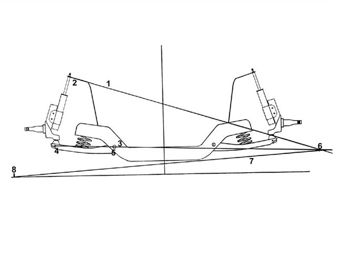
To find the front roll center of a MacPherson strut suspension, draw a line (1) perpendicular (at a 90-degree angle) to the top pivot point (2) of the right-front strut and extend it out until it intersects (6) with a line (3) extending through the two pivot points of the right-front lower control arm (4 & 5). The intersection of these two lines is the instant center. Then draw a line (7) from the instant center back to the right-front tire centerline (8). This line is called the swing-arm length. This same process is applied to the left-front suspension. The point where the swing arms for the left front and the right front intersect is the true front roll center.