At Circle Track we have the luxury of meeting teams at all levels of racing from all across the country. Many of you are wizards with a welder and fabricate anything. Many of you can rebuild a race engine with your eyes closed and practically tune a carburetor while the car is still running laps under caution. And many of you out there can run crossweight calculations in your head like the rest of us say our ABCs. But what we haven't heard is many racers claim to be electrical experts. Don't get us wrong, we know plenty of you are capable, it's just that very few racers are either comfortable working with electrical systems or actually enjoy it.
Still, it's important to be able to have confidence that you can wire your race car correctly so that you aren't wasting time chasing those annoying electrical gremlins that usually seem to pop up at the worst possible time. For a little help we caught up with someone who actually calls himself a wiring and electrical-systems specialist. Rick Elgin owns RaceWire Technologies, and he spends his days wiring practically everything on circle track race cars, drag cars, hot rods, and anything else with a battery and a starter.
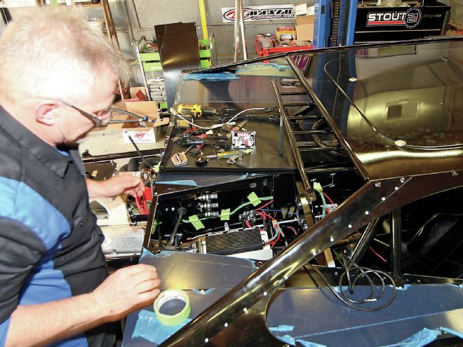
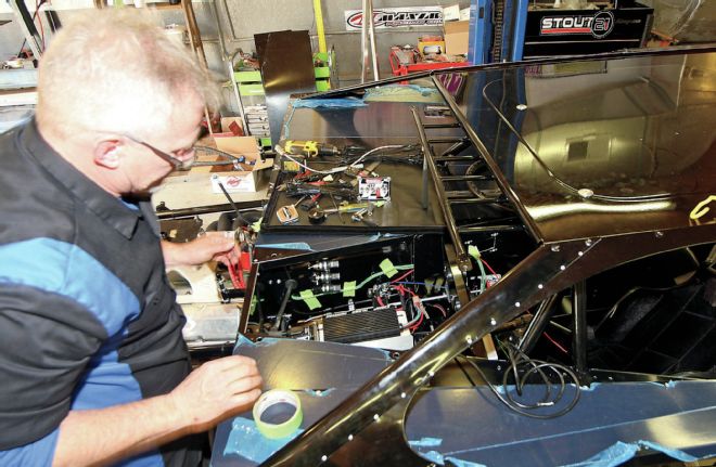
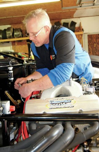 Wiring a race car is a thankless task, but believe it or not, some people are actually good at it. Rick Elgin of RaceWire Technologies is one of those people, and he was willing to share his secrets with us.
Before starting RaceWire Technologies, Elgin spent several years at Joe Gibbs Racing as part of a small team that handled wiring all the Cup cars. While there he not only learned all the tricks, he also helped develop a few of them, and now he's applying his expertise to help Saturday night racers.
Elgin is based out of the Charlotte, North Carolina, area and travels to the surrounding states to wire cars for racers in their shops. For this story we met him at the shop of Chris Ferguson Motorsports in Mt. Holly, North Carolina. Ferguson races Dirt Late Models and like most Saturday night racers, his program is a small operation and most of his help comes from his family. They could handle wiring the car themselves but every dirt car lives a hard life between racing and the wash pit, and they wanted to make sure they had the most dependable system possible to avoid the potential of electrical problems costing Ferguson potential victories.
This story isn't going to attempt to show you every step of wiring a car front to back. Every car is a little different, and honestly, that would be a pretty boring read. Instead, we're going to pass along tips Elgin provided us and show you what he uses and why. For example, Elgin says he often helps racers fix problems with existing systems, and the problem he sees most often is poor grounding of electrical circuits. Many racers will use several grounds—maybe one for the starter, one for the gauges, and another for the ignition box—but if one ground isn't working as effectively as it should that extra electricity can bleed back into other circuits. To eliminate this Elgin prefers to always run a tracer wire to each ground, and often back to the battery, to make sure everything stays equalized and is grounded optimally. We've got lots more for you, so read on.
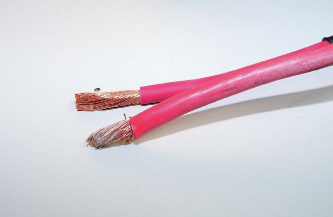
Point 1: Chris Ferguson’s Warrior DLM chassis that Elgin is working on is brand new with no old wiring to pull off, but Elgin did save some samples from previous projects for us. Like most people, when beginning a project Elgin begins with the battery and starter. He recommends always using power wires that are at least 4 gauge—especially if you are using a gear-reduction starter or a 16-volt battery. Also, look for high strand count wire (in back) compared to standard wire with thicker strands of wire. The higher strand count wire is more flexible and more easy to work with, but more important, the increased number of strands conduct electricity more efficiently.
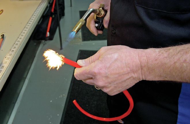
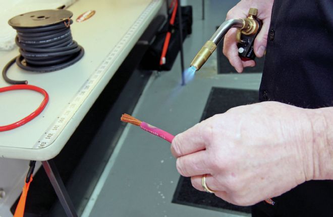
Point 2: For your race car, you should also look for welding grade cable. The other option is audio cable, but that doesn’t have the same heat resistant sheathing as welding cable. Audio cable may be fine in a Volkswagon Jetta with four 20-inch subs the owner uses to annoy people in the mall parking lot, but it doesn’t belong in a race car where fire and excessive heat is a real issue. As proof, Elgin hits a piece of audio cable with the torch he uses on shrinkwrap tubing and it immediately lights up.
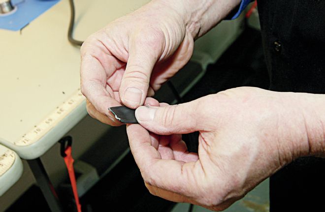
Point 3: When Elgin pulled the torch away after a few seconds the flame died down immediately. But then he showed us the real weakness of the audio cable cover. Elgin gave the cover a squeeze between his fingers and when he pulled his hand away the cover retained the print from his thumb. For racing, you need a cable that can withstand extended exposure to heat without breaking down.
Point 4: In comparison, when given the same treatment the welding cable never caught fire but only turned brown and didn’t get soft like the cover of the audio cable.
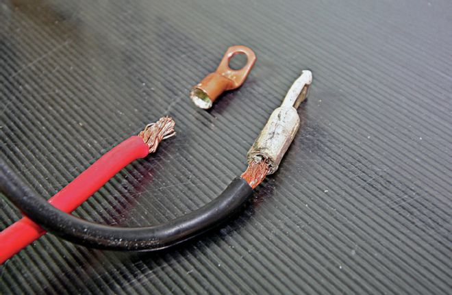
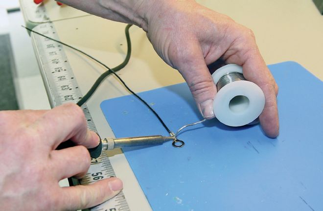
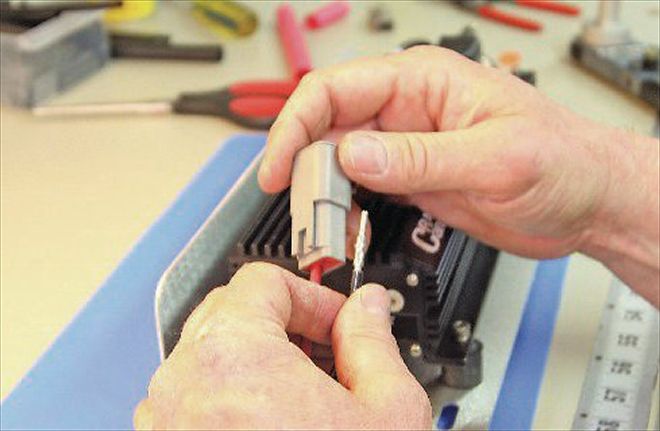
Point 5:. Elgin uses a crimping tool to permanently attach the terminal ends to the power and ground cables, but it is a specialized tool that many racers simply do not have. Instead, a common tactic is to use a cupped terminal like you see here. Racers will put the terminal in a vise with the cup facing upward. Then they will heat the terminal with a torch, melt a puddle of solder into it and then jam the cable into the cup until the solder cools. Unfortunately, this bond is quite weak and often breaks. The mistake, Elgin says, is not heating the stripped portion of the cable too. When the cable is cold the solder hardens to the outside of the bundle of wires only. But if you heat the wires in the cable, it will wick the solder up the cable and in between the strands, making the bond much stronger.
Point 6: Elgin runs a high voltage Anderson Quick Disconnect at the battery. This way an emergency battery swap at the track doesn’t require any tools (assuming the battery hold down uses wing nuts).
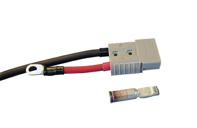
Point 7: Here’s a closer look at the Anderson Quick Disconnect Elgin uses. That’s the terminal that goes inside the housing. For power wires, the connections need to be beefy so they aren’t impeding the flow of current.
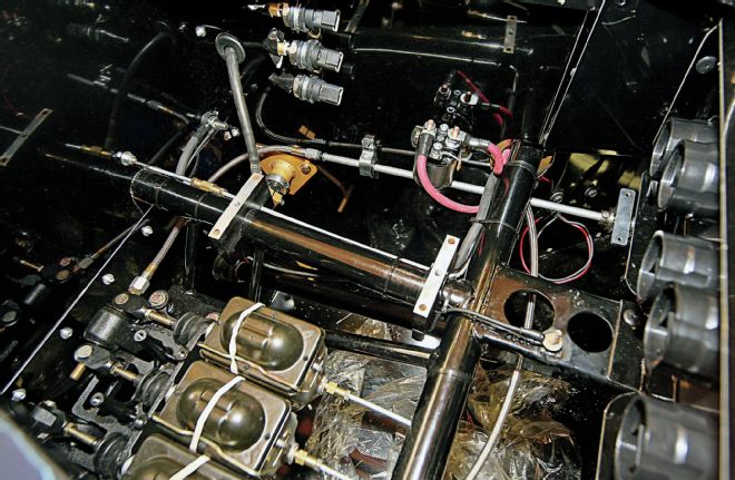
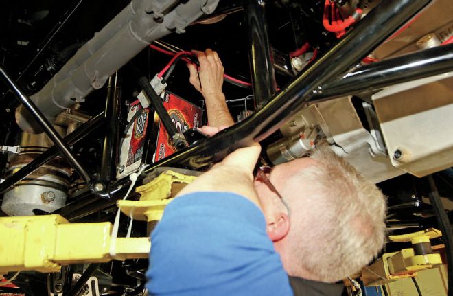
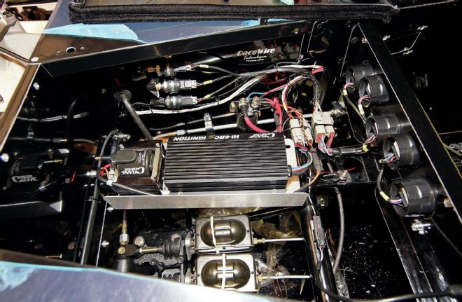
Point 8: The solenoid is mounted in a protected area just behind the dash. The cable to the starter is on the left. Elgin will use the connection for the battery cable (always hot) as a terminal post for everything else that needs power. Just above the brake and clutch master cylinders is the mount for the Crane ignition box and coil.
Point 9: Elgin cautions that the weak point in any wire is where the flexible wire goes into a hard point. Most crew know to be careful with wire where it connects to a hard metal terminal, but if solder is allowed to wick up the strands in a wire, it can create a hard point further up the wire that’s hidden by the insulator. Elgin uses solder to help ensure a good, durable connection on all of his crimped fittings, but to keep the solder from wicking too far up the wire he applies solder on the end opposite the wire. As we mentioned earlier, heat will cause liquid solder to wick up the wire, so as soon as the solder is applied Elgin quenches the piece on a moist sponge to get rid of the excess heat.
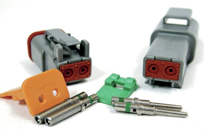
Point 10: NASCAR Cup Series teams have gone almost exclusively to Deutsch connectors like these, and Elgin keeps a wide variety of these connectors on his trailer for all of his connections. Deutsch connectors are incredibly robust. Beside being very efficient conductors of electricity, they are resistant to fire, vibration, dust, chemicals, and all-around abuse. And for dirt track racers that like to hose everything down with a pressure washer after a hard night of racing, these connectors are just water resistant, when installed correctly they are actually waterproof down to three feet.
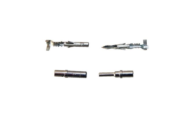
Point 11: We know lots of racers who still depend on Weatherpack connectors. Weatherpacks are definitely better than nothing, but here’s a visual example why top teams have moved to the Deutsch connectors. At the top in this photo are a male and female Weatherpack terminal connector. Below that are the equivalent for a Deutsch connector. The Weatherpack plugs are rolled sheetmetal with cut out “springs” designed to ensure good contact between the two components. The Deutsch plugs, meanwhile are solid steel and there are no issues with fatigue or wear no matter how many times the two halves of the connector are separated and rejoined.
Point 12: Once the connector is crimped to the end of the wire, it inserts through the back of the plug housing and a plastic piece is inserted to lock it into place.
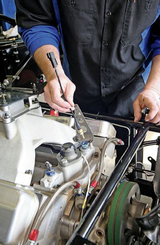
Point 13: When trying to determine how to route wires through a car it can be impossible to correctly determine the length you are going to need with a tape measure. Instead, Elgin uses rope to simulate the wire (it’s much easier to work with) and once it gets it routed exactly like he wants it, he marks the ends, removes the rope from the car and cuts his wire to match.
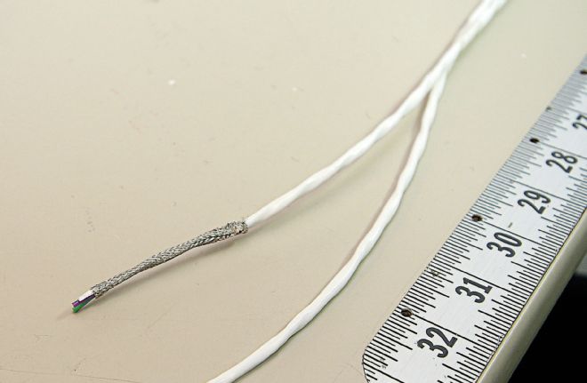
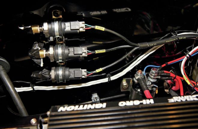
Point 14: Providing precise timing to the ignition box so that it can accurately time the spark is critical for engine power. This engine uses a pickup both from a crank trigger at the front and an MSD distributor. One is timed slightly different from the other so the driver can retard the engine timing from the cockpit with a switch if he needs to. For the pickups Elgin uses paired wires with extra shielding so that the electrical pulses travelling down the plug wires won’t throw off the signal.
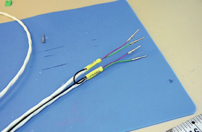
Point 15: Here are the wires for the pickups right before Elgin finished installing the Deutsch connectors. These leads will go to the switch panel in the cockpit. The black wire is a ground that connects the two and will provide additional shielding to protect from stray signal. Notice how each wire is labeled to eliminate confusion. Elgin covers each label with a piece of clear shrinkwrap to protect it from wearing off.
Point 16: Speaking of shrinkwrap, Elgin uses it to cover all his crimps and connections. It serves to keep dust and dirt from contaminating the connection, to keep moisture out, and to cover any bare wires so that there is no chance of a short. But the shrinkwrap Elgin uses is also unique. It’s a tough double-wall material that actually has a heat activated glue on the inside. So the wrap not only shrinks to cover the wiring connection, it also actually glues itself to the wire and terminal to provide optimum sealing.
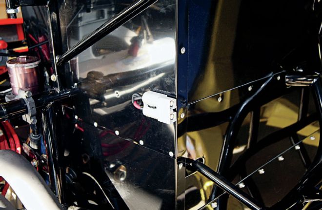
Point 17: The team wanted a battery charger connection placed on the firewall. Elgin uses another Anderson Quick Disconnect here, but notice the wire is smaller (and lighter) than the 4-gauge battery wire. The team says they will only use this for charging the battery. If they thought they would ever use it to jump start the car Elgin says they would need to upgrade to a 4-gauge cable.
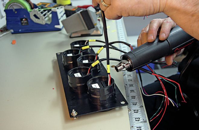
Point 18: Ferguson will be using Spek-Pro gauges from ProParts in the car, and they will be removed whenever the car is washed to protect them from water. Each gauge has its own plug, so Elgin labels each appropriately so it will be easy to reinstall the panel.
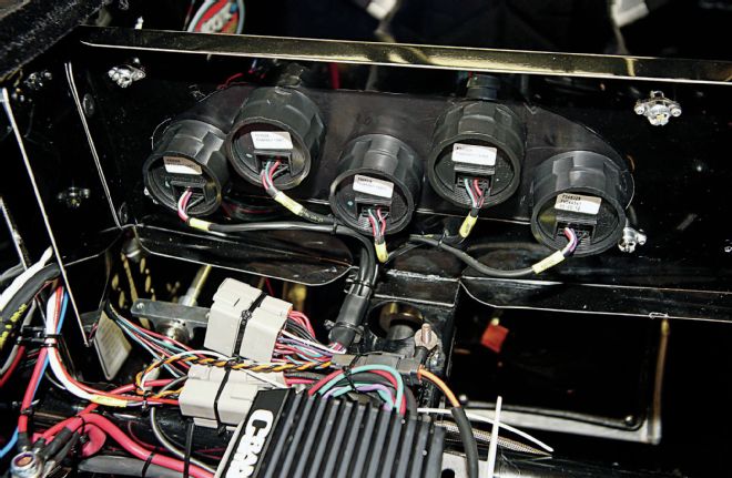
Point 19: Here’s the gauge panel inside the car.
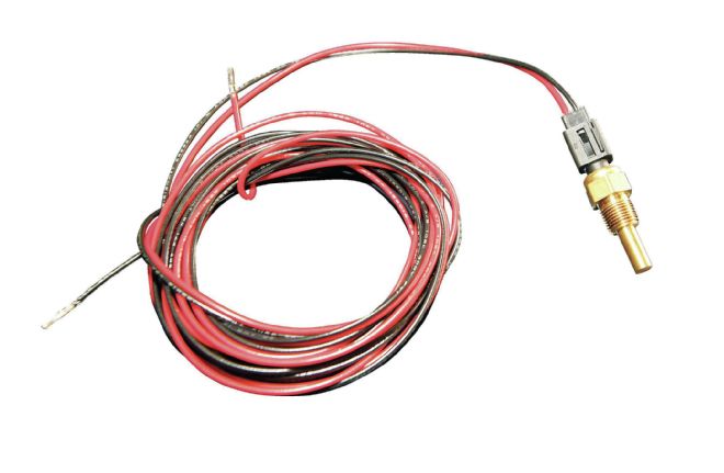
Point 20: This is a temperature sensor typically used for oil and water. Notice how close the plug is to the sensor. This is often a breaking point.
Point 21:These are the connectors Elgin fabricates himself instead. They use a longer lead so that they are easier to unplug and are much more robust.
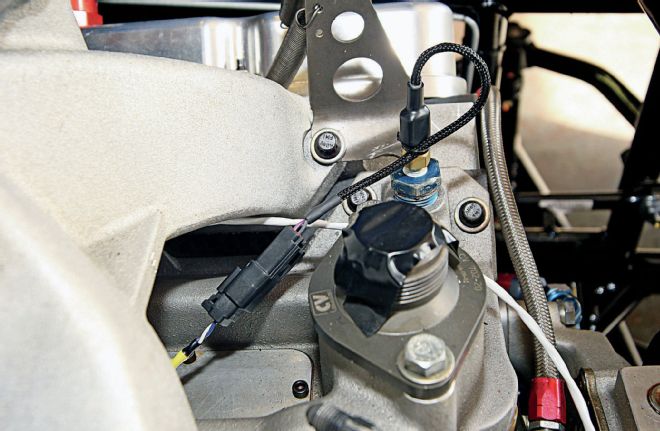
Point 22: Elgin zip-ties the sensor wire into a loop to keep stress off the hard point where the wire meets the metal connector.
Point 23: Here’s the wiring setup to the sending units for fuel, water and oil pressure.
Point 24: And here’s the completed system under the dash.
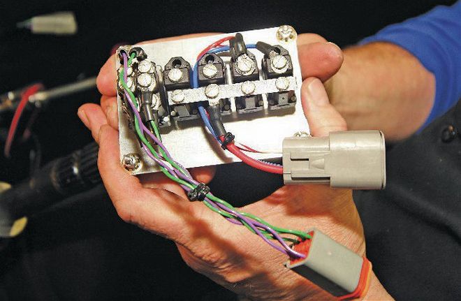
Point 25: This is the switch panel. Notice that Elgin wired nothing directly to the switch panel. Everything goes to a connector first so that the switch panel can be easily and quickly removed. The wiring on the left is the selector for which ignition pickup will be used (crank trigger or distributor) and the others are on/off switches for the ignition and brake cutoff.
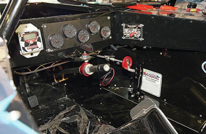
Point 26: And once everything is finished and tucked away, here’s the view from inside the cockpit.