I have to admit that prior to my '68 C10 LS project, I was totally ignorant when it came to AN fittings. Typically, when it came to plumbing a fuel system, my vocabulary was limited to NPT and hose barb fittings. The end result was usually a few leaks and a less than stellar setup, for a carbureted system no doubt. When it came to an actual EFI setup, I was in the dark. I knew EFI systems required more pressure and thus, naturally a different way to run the fuel lines. But just how, I was unsure.
So, when it came time to plumb the supercharged LS327 in my '68, I opted to leave it in better hands and tapped the guys at Aeromotive to help me set up the fuel system. As it turns out, it's pretty simple.
We'll start at the beginning of the fuel's journey, the fuel tank. For our project, we chose to move the fuel tank out of the cab for a couple of reasons. One was to gain more room behind the folding bench seat. The second was to get the fuel cell away from the passenger compartment. While it's easy to argue the fact that putting it at the very back of the truck isn't the most ideal location, I take comfort in the fact that it's now separated from me and my passenger. It also solves the fuel smell that can accompany an in-cab gas tank. Furthermore, when it came to fuel pump selection, we opted to use an in-tank pump; something that isn't so easy with the stock C10 tank. We solved all of these issues by using an Aeromotive fuel tank that was designed for a '69 Camaro ("Muscle Car Cells for Classic Trucks," April '13) equipped with an in-tank 340 Stealth fuel pump.
From the tank, the fuel is picked up by the 340 Stealth pump and sent hurtling down the AN-8 stainless steel braided line through a 10-micron fuel filter. Flowing upwards of 2,000 lb/hr, this added filter is cheap insurance to protect the fuel injectors that are just down the line.
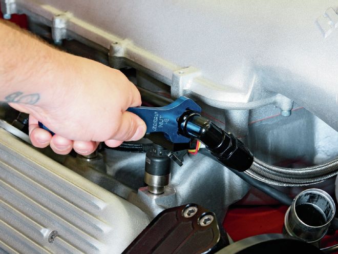
Next, the fuel travels through the Holley 5⁄8-inch diameter fuel rails, with one of two conclusions; either the fuel is metered through one of the eight 42-lb/hr injectors and into the engine or it's bypassed through the Aeromotive A1000 Injected Bypass Regulator back to the fuel tank by way of a stainless steel braided AN-6 line.
Once the system is mapped out, it's easy to see how simple it really is, even for a guy like me. If the proper elements are used in the proper location, it's easy to set up a foolproof, high-performance EFI fuel system on any truck that will last for years to come and look great to boot!
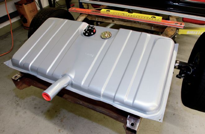
1. You'll remember the '69 Camaro fuel tank from Aeromotive we installed in the C10 a few months back. Well, now it's time to hook things up.
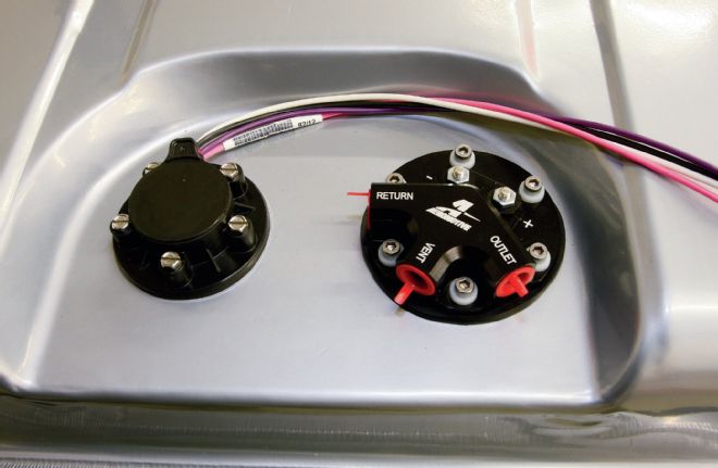
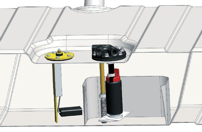
2. Since we're using a Classic Instruments gauge cluster, we opted to swap out the stock fuel sender with Classic's floatless sending unit. This view also affords a good look at what's going on atop the 340 Stealth fuel pump, which resides inside the tank. We're going to run the outlet line (AN-8) up the driver side, while the return line (AN-6) will come down the passenger side after running through the LS' Holley fuel rails. The vent line will run to Aeromotive's supplied aluminum vent that needs to be installed above the tank's highest point.
3. This happens to be the filler neck that exits through the rear bumper. We opted to install the bracket and vent on the rear crossmember and connected it to the vent outlet on the tank using AN-6 stainless steel braided line and fittings from Aeromotive.
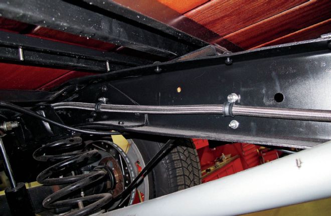
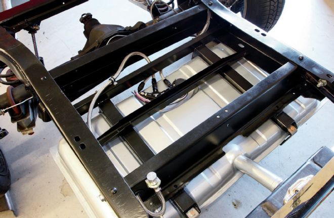
4. Once the lines are connected at the tank, it's a simple task of running them down the framerail. Here, the AN-8 line heads from the tank…
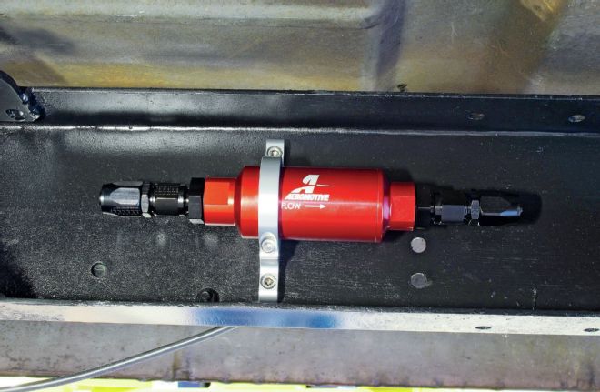
5. …to the Aeromotive fuel filter. Able to flow 2,000 lb/hr with a pressure drop of less than 1 psi and machined from 6061-T6 aluminum, the 10-micron fuel filter will mate to our AN-8 braided line via AN-8 to ORB-10 fittings.
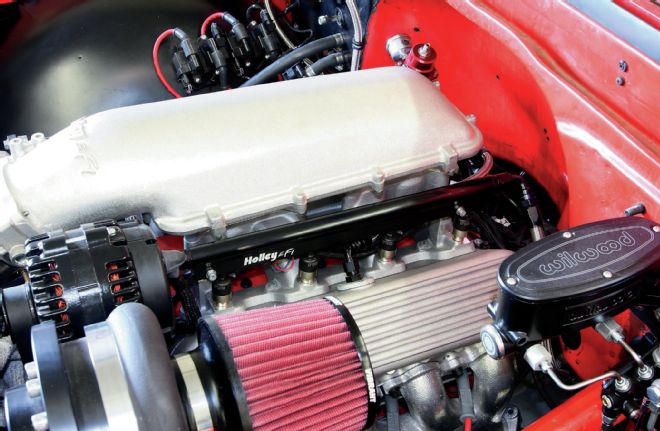
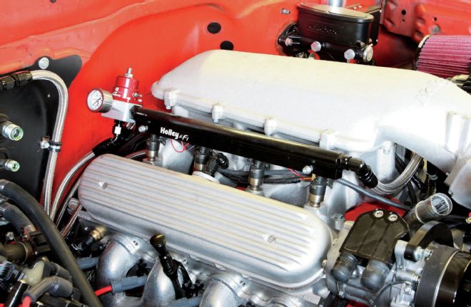
6. From the fuel filter, the line travels along the framerail to the Holley Hi-Flow fuel rails, connecting via ORB-10 fittings. Their 5⁄8-inch diameter fuel passage provides the flow capacity for high-horsepower applications and won't constrict the fuel flow coming from the AN-8 line. Four 42-lb/hr injectors are fed by each fuel rail, more than enough for our supercharged 327.
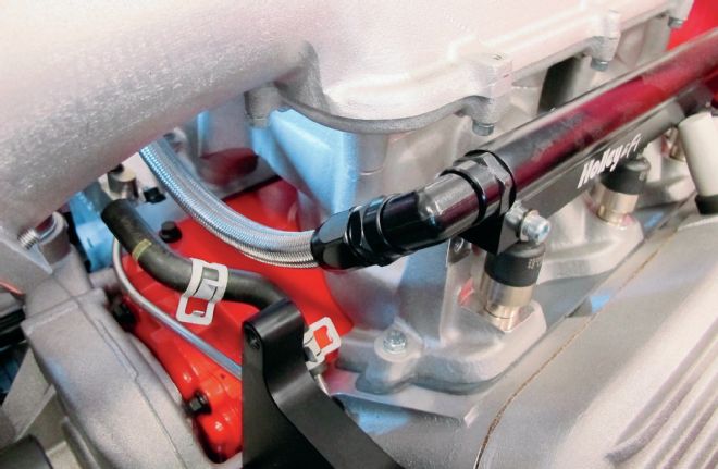
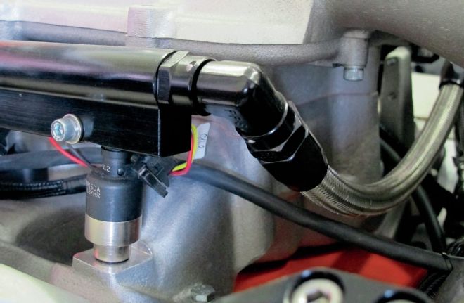
7, 8. Another AN-8 line mates the driver-side fuel rail to the passenger-side fuel rail ...
9. … and another quartet of 42-lb/hr injectors.
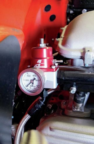
10. The big difference on the passenger side is the fuel regulator. Here, the A1000 Injected Bypass Regulator mates to the Holley fuel rail via an ORB-10 to ORB-6 swivel adapter. The regulator ensures that both fuel rails maintain the pressure they need to provide the injectors before it bleeds off the excess via an ORB-6 return port out the bottom of the regulator. From here, the excess fuel is bled back into the fuel tank via AN-6 stainless braided line, completing the fuel system.
AN-6 versus AN-8
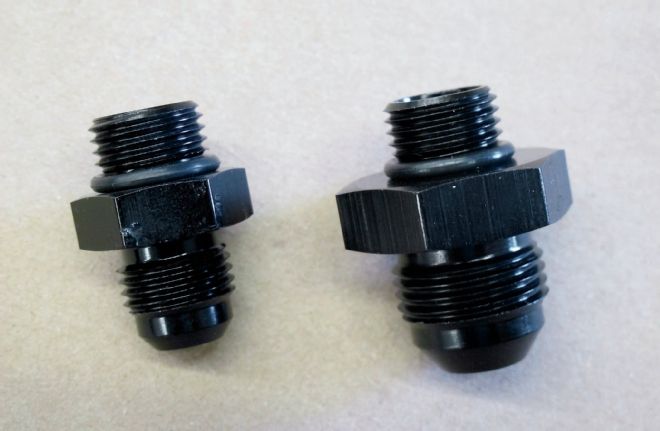
11. Here's the difference between an AN-6 and AN-8 fitting. Remember that the AN-6 is a 3⁄8-inch ID while the AN-8 is 1⁄2-inch. While most mild (< 400 HP) engines would be fine with an AN-6 line, we opted to err on the safe side and run AN-8 on the inlet side. Since the return line is basically a bleed-off, AN-6 is fine to use on that end of things. Fuel starvation can kill engines, so it's cheap insurance. Note that both fittings mate to an ORB-6 on top.
Mating Stainless Braided Line To an AN Fitting
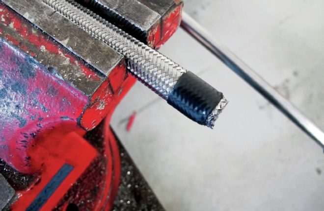
12. When it comes to mating stainless braided line to an AN fitting, the first step is to cut the line to length. First, the line is tightly wrapped with electrical tape to keep the cut end from fraying.
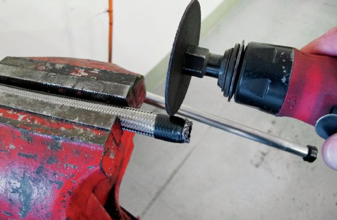
13. Then, the line is cut to length using a 4-inch cutoff wheel. Note that the cut is made through the section that has been wrapped in electrical tape.
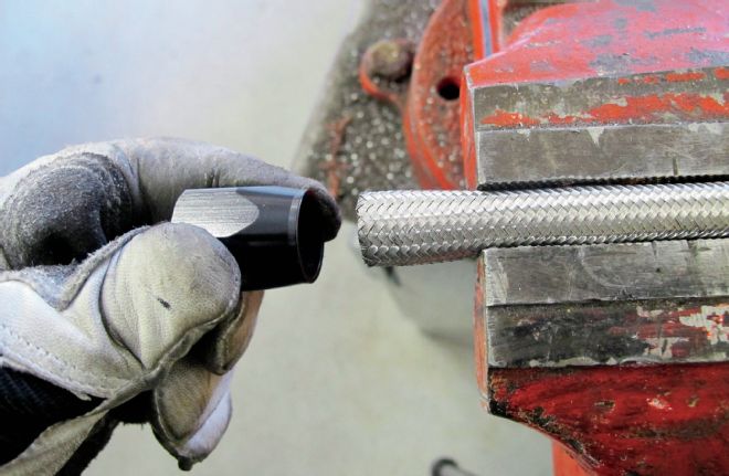
14. Once cut, the electrical tape is removed and the socket is pushed onto the hose. If fraying is kept to a minimum, the socket will seat fully onto the hose.
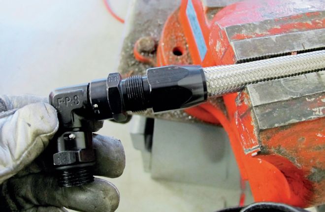
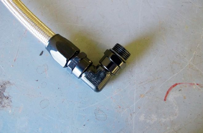
15, 16. Next, the insert is threaded into the socket, drawing the hose tight and thereby completing the connection. In this example, a 90-degree ORB-10 to AN-8 fitting is being used.
Feeding The Beast
17. Submerging the pump inside the tank not only increases pump longevity by keeping it nice and cool, but also reduces noise and vibration that can be attributed to a frame-mounted fuel pump. Housed inside a baffling system in the tank controls fuel slosh and keeps the 340 Stealth pump submerged during even the most aggressive driving. This results in consistent pump performance even at low fuel levels.
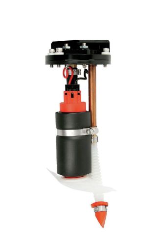
18. The 340 Stealth electric fuel pump uses a turbine pump mechanism for increased durability and performance, an impressive 340 lph. A pre-pump filter sock assembly keeps any debris from being sucked into the pump assembly, improving pump life and performance as well as helping protect the rest of the fuel system.