If your memory is short like ours, know that in 2012 we showed how Marshall Woolery at Thun Field Rod & Custom in Tacoma, Washington, transformed the suspension and chassis of a 1939 Chevrolet coupe ("The Stovebolt Saga", May-Aug. '12 issues). Math, more than memory, shows that we haven't visited the subject in nearly a year.
The Stovebolt Saga is back for a proper exhaust system. Any ol' exhaust shop could've bent up a workable system in an afternoon but we think this application warrants something more.
It's largely because of the engine. It's a healthy example of a pre-'64 six-cylinder Chevrolet, aka a Stovebolt. These engines really aren't different from any other but their relatively small size underscores the importance of preserving as much power as possible. In exhaust terms that means building a system with pipes just big enough to handle the engine's volume at fast speeds yet small enough to generate the torque-building velocity at slow speeds. It's a balancing act that's challenged builders for time immemorial.
It's also something functionally impossible to achieve with tubing bent by conventional means. Press benders at exhaust shops and even the fancy tube benders at chassis shops basically mash the tube into an oval through the bend. Circumference being equal, an oval has less surface area than a circle. That restricts flow with predictable consequences. Increasing tube size to compensate for the bends would kill the gas velocity through the straight sections, which would let the torque dribble lazily out the tailpipe.
The solution is a mandrel bend. A mandrel bender resembles the tube benders in chassis shops but it has a die that supports the inside of the tube so it stays round.
Unfortunately, true mandrel benders are heavy-industry tools exclusively. Luckily companies like Patriot Exhaust Products sell mandrel-bent tubing segments. Since the tubes remain round at all points they can be cut and assembled to straights or other bends in near countless combinations. Read the "How to Cut Mandrel Bends" entry in this article to learn one way how to do it.
Piecing together a system from mandrel bends costs more time and money but the advantages are significant. Anyone with a saw, a grinder, and a welder can do it. And a system built of mandrel bend segments can potentially fit a lot better than a press-bent system.
Why Not a Y?
This engine's header inspired us to think creatively. It divides six pipes into two collectors, which technically isn't as efficient as routing all of the tubes into one. In really rudimentary terms a collector gives each cylinder the benefit of pumping its charge into a low-pressure, high-velocity stream generated by the exhaust event that preceded it.
Merging the pipes from two collectors into one larger pipe (a Y-pipe) achieves much of the benefit of running all of the header pipes into a single collector. In fact, that's what most vehicle manufacturers did for years to build street-friendly torque with V-8 engines.
Some really elemental calculations indicated that two primary pipes with a 1 7/8-inch ID feeding a single pipe with a 2 1/4-inch ID would flow enough yet still build fair velocity. Assuming a 16-gauge wall thickness, that's two 2-inch primary pipes and one 2 3/8-inch main pipe.
But there's a flaw with that secondary-pipe diameter. A 2 3/8-inch-diameter pipe is quite hard to find, regardless of wall thickness. Larger pipes like that can also make a Stovebolt drone like a boat or tractor. They're also more likely to induce interior resonance. At the very least large pipes rob Stovebolts of their characteristic exhaust rap, which, for some, is reason enough to endure such an antiquated engine.
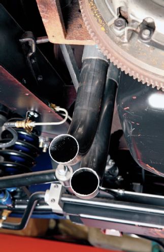
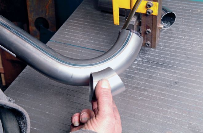
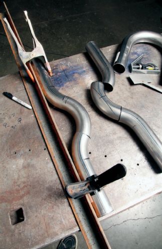
1. The headers in this application dump straight down but because the pipes need to go straight back Marshall Woolery cut a 2-inch-diameter U-bend to make two 90-degree elbows. Refer to the sidebar on page 30 to learn how to cut tubes properly.
2. The elbows slip into flanges that bolt to the header. They appear to sit at different heights but they're even. They do, however, point in slightly different directions for a reason.
3. Here's why the pipes point two ways: the collectors line up in the direction of the pipes. So Woolery let the rear one (left) point straight back while the forward one points a few degrees to the passenger side.
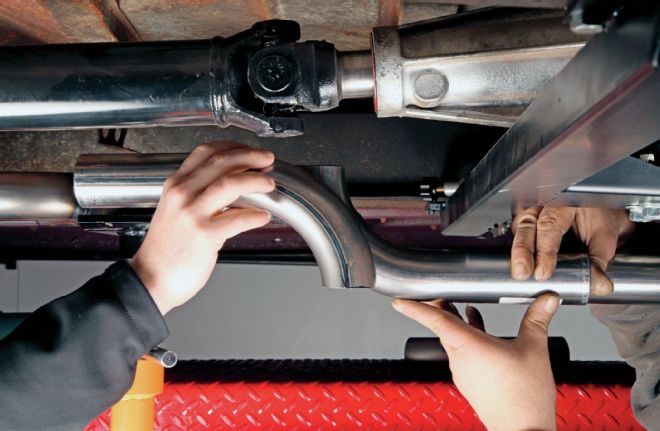
4. Because the rear pipe can go straight back at the engine's mounting angle, Woolery simply jacked up a straight pipe to it and marked the fit points. Technically he could've tacked the pipe in place but he left it loose for the time being.
5. The other pipe requires a little finesse. It needs a slight bend to straighten it. Woolery measured the offset and cut a piece slightly longer than necessary. Again, refer to the sidebar to learn how to cut bends properly.
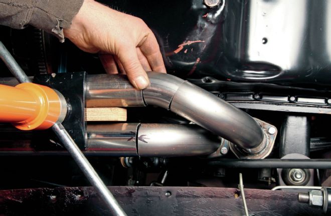
6. Woolery cut the piece long so he could trim it until the second pipe landed about 3/4-inch away from the first. The gaps at the inside radius indicate that this pipe needs to be trimmed a bit more to maintain the 3/4-inch gap between the pipes.
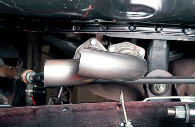
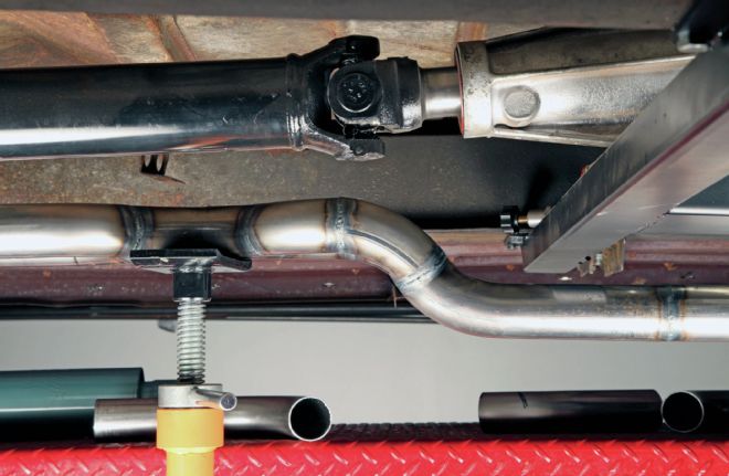
7. Because the downpipes turn at 90-degree angles the first part of the exhaust follows the engine-mounting angle. To level the pipes Woolery cut another bend. The fixture in the sidebar shows how to mark a tube cut at a pretty precise angle.
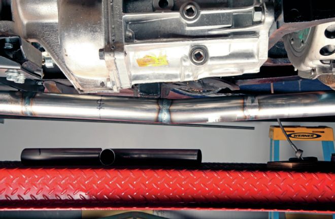
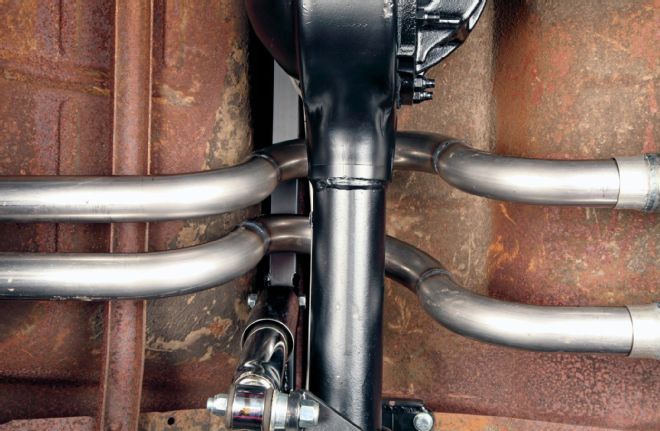
8. Here's where the two tubes came together at the weld.
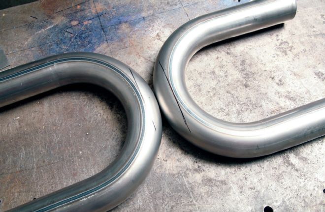
9. Cut and rotate a bend 180 degrees to create straight offsets of various amounts. You can do it by distance. First determine the required offset and half that figure. Mark each tube where its centerline rises or falls by that amount. Then draw a line through that mark along the radius centerline.
10. You can also calculate offset by angle if you know the bend radius. A 180 cut into two 90s will create an offset equal to the bend's radius, in this case 3 inches. The pipe needed to rise 2 1/2 inches or 83 percent of 3 inches. Well 83 percent of 90 degrees works out to 75 degrees. So Woolery cut both pipes to 75 degrees to create his 2 1/2-inch offset. Note that this shot shows the X attached.
The X Factor
Though technically compromised, split headers offer a construction option that a single-collector header can't: we can run an X-Pipe.
An X-Pipe combines both headers' downpipes into a collector of sorts and then splits them back into two exhaust pipes. The collector's smaller diameter briefly increases the velocity of each exhaust charge, which reduces the dynamic pressure at that point. That, like the header collector, gives each exhaust charge a lower-pressure/higher-velocity place to go. From there the exhaust gases that would ordinarily travel along one pipe get the option of going through both exhaust pipes. The design gives the engine its best chance to build power across a broad speed range, something that made NASCAR builders adopt it. And that really benefits smaller engines that can't afford to spare any power.
As appealing as the power gain is it's almost secondary to another reason: smaller exhaust pipes. The engine doesn't care what the exhaust looks like downstream of the X so long as it maintains the right combination of volume and velocity. The 2 1/4-inch inside diameter of the pipe we calculated has 4 square inches of internal area. A pair of 1 5/8-inch inside-diameter pipes (16-gauge 1 3/4-inch OD pipes) has 4.15 square inches of area, which is close enough for our purposes. Yes, that means the pipes neck down after the X but remember that the X gives each exhaust event the option of going through both pipes rather than just one.
Most suppliers, Patriot included, carry bends in all of these sizes. And because the two pipes are small they'll prevent this Stovebolt from droning like a heartsick calf. For good or ill the X will also diminish the crackle that Stovebolts are prone to make when split into two smallish pipes.
Unfortunately, X-Pipes for smaller, lower-performance engines like this don't exist due to a lack of demand. That means we had to build ours. It really isn't tricky in the least, though. In fact building your own X gives an exhaust the potential to fit a car like a glove.
It took some thinking but we achieved our goals without sacrificing power or sound, though we don't have the opportunity of demonstrating the sound here! So you'll have to take our word for it: mandrel-bent exhaust systems and X-Pipes offer benefits beyond bragging rights.
11. Woolery built the X by first marking two 2-inch U-bends perpendicular to their radius. He brought the lines back to the tube's centerline.
12. He then plotted more lines on each side of the area at the 45-degree mark. Then he cut along those lines.
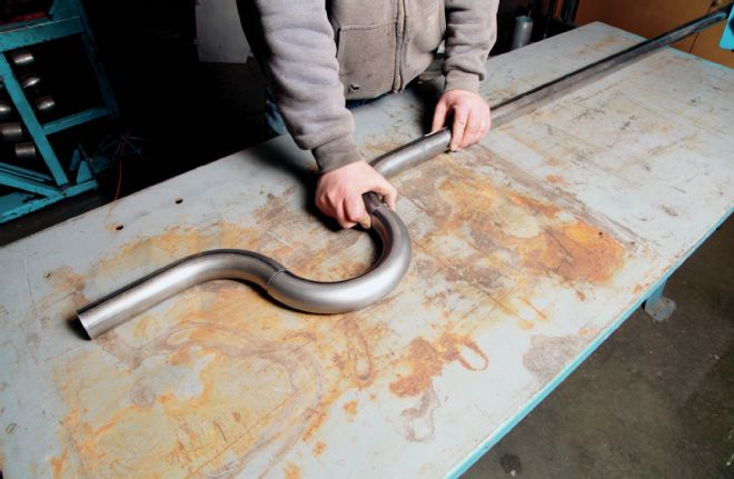
13. Rotating those cut ends 180 degrees transforms a U-bend into a straight with a jog in it.
14. It wasn't necessary at this point but Woolery welded up one leg of each jogged section prior to cutting along the line perpendicular to the tube's centerline.
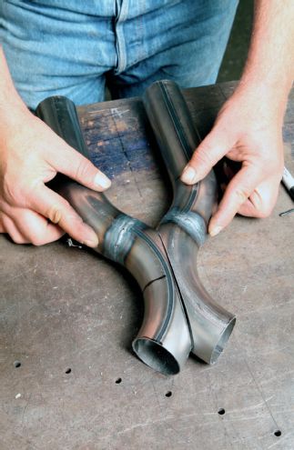
15. The modified U-bends meet at their cut sides like so. At this point he welded the halves together to form the core of the X-Pipe.
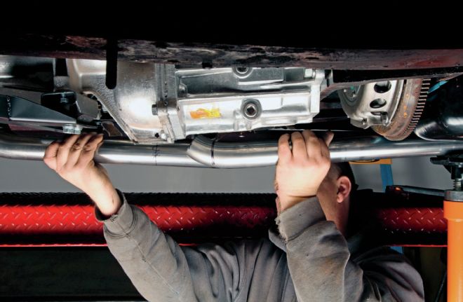
16. After Woolery welded the second set of legs to the other side of the X-Pipe he jacked up the finished assembly and welded it to the downpipes. Until now all photos show the front of the car to the right but this shows it to the left.
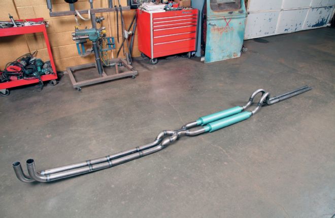
17. We wanted a traditional sound so we chose traditional mufflers: Patriot's Smithys. We built the X from 2-inch pipe to suit the Smithy inlets and necked down the outlets to fit the smaller 1 3/4-inch pipes. We designed the system around the longer 26-inch cases so we can go shorter if need be.
18. The outlet pipes are pleasantly simple. Woolery cut one U-bend apart at the middle to create the rise and return. He cut the legs off another U-bend to make the arch. He welded that pipe together straight.
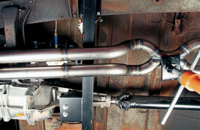
19. The pipe closest to the car's centerline clears everything perfectly, hence the straight shot. The one on the outside would've hit the damper body so Woolery offset it a touch.
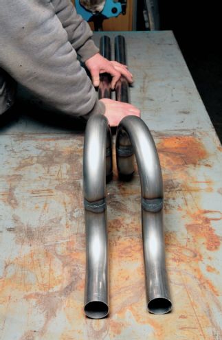
20. The offset was simple: Woolery just kicked it over enough to clear. That put the tailpipes closer together, a look that a lot of six-cylinder enthusiasts embraced in the past to distinguish their cars from the V-8–powered machines. The foreground is the muffler side.
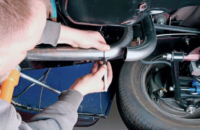
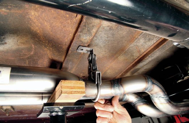
21. Woolery then jacked up and aligned the tailpipes. He set the gap between the pipes the same way as he used in the front: by clamping them together with 3/4-inch plywood between them. He welded tabs between the pipes to maintain their alignment.
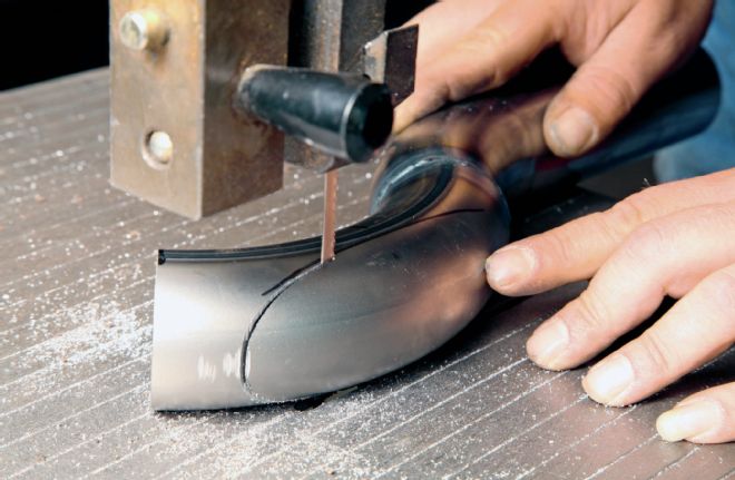
How to Cut Mandrel Bends
It's easy to build a system from mandrel bends but it's not idiot proof. It requires dogmatic adherence to one technique. Luckily it's a simple one.
Unless you're intentionally breaking the rules (which is rare) then always cut tubes perpendicular (90 degrees) to their centerline. Then the cut end will emerge perfectly round and will match the wend of any other tube cut perpendicular to its centerline whether straight or bent.
It's easy enough to plot a perpendicular line on a straight tube: just lay a combo square head on the tube and draw along the ruler. But that's not possible in a bend. In these cases we have to reference the radius centerline. The radius centerline represents the line from the radius' center point as plotted across the tube.
There are several ways to do that but a template makes life so much easier. It takes a board, compass, square, protractor, pencil, nail, and a length of string. A template can be used for multiple pipe diameters and radii. Just draw the appropriate reference points for each pipe's dimension.
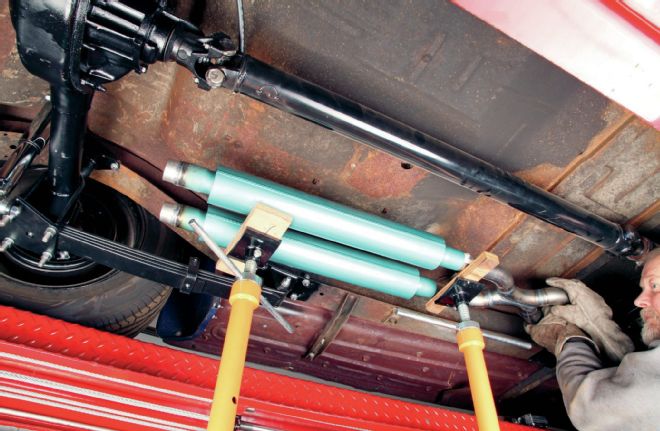
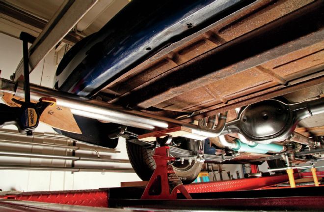
22. Finally he clamped the system and hung it. Many enthusiasts dismiss simple exhaust-shop hangers but they isolate the system from the rest of the car real well, let the hot pipes expand with heat, and last for years without any maintenance.
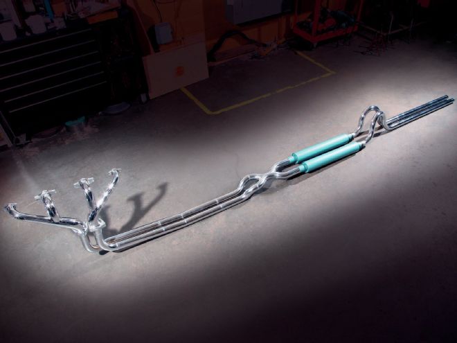
23. This is the way the system looks without the header flanges. Woolery sent it to Don Meth at Show Quality Metal Finishing for the flash plating as seen in the first shot. Though not quite as durable as ceramic it costs far less and looks like it was ripped out of an old magazine.
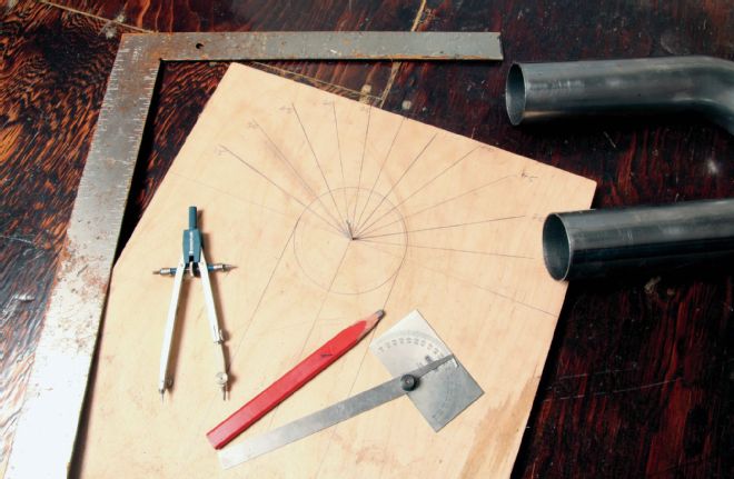
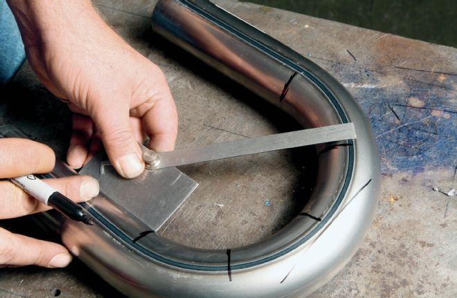
24. Strike X and Y axes on a board and add marks at 15, 30, 45, and 60 (shown) or better yet print out a compass and glue it to the board. Draw a circle the size of the bend's inside radius. Pop a short nail in the center point and tie a string around it. The parallel lines make alignment simpler.
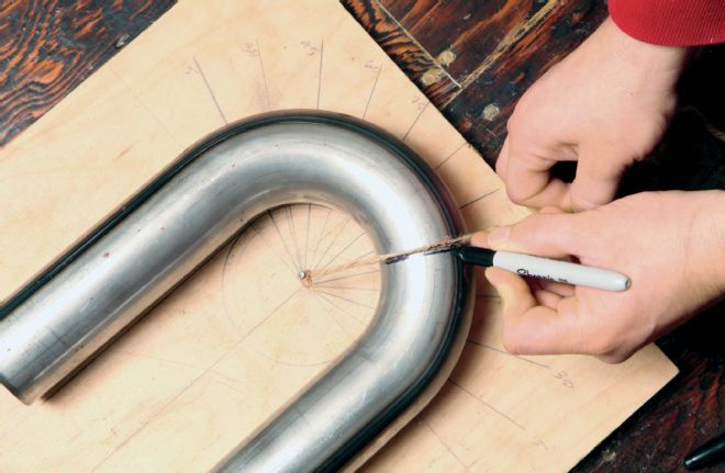
25. Align the tube over the parallel lines and circle, pull the string over the tube to the desired angle, and draw the line. Remember to cut on the side of the line closest to the string.
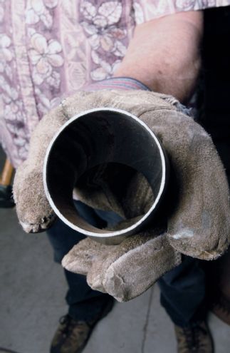
26. Mark the tube properly and its cut end will emerge just like this, perfectly round and ready to meet another tube at any angle. It can't get much easier than that!