It's the classic routine. Small-displacement engines make great power for what they are. When first introduced to our project, the stock LS327 made 327 hp at 5,500 rpm with 347 lb-ft at 4,600 rpm. Compare that to the standard Gen I 350ci deluxe crate engine offered by Chevrolet Performance that makes 290 hp or the next step up 350 HO that makes 330 hp and our LS327 is already a game ahead in the horsepower department. This is mainly due to an efficient production-based cylinder head design, a Chevrolet Performance Parts cam, and Grafal-coated pistons. This is despite the fact that it suffers from small-bore syndrome that tends to detract from good port energy into the cylinder.
Despite these shortcomings, the 5.3L LS327 still has plenty of opportunity to make more power. The best way to accomplish this is to simply introduce more air and fuel into the engine. While we could increase the stroke and bore to give the engine more cubes, that requires more time, money, and resources and really negates the point of buying a crate engine in the first place. Instead, we decided to leave the foundation of the motor—the bulletproof bottom end—intact and concentrate on upgrading the bolt-on components to help the little 5.3L breathe a little easier.
While high-winding, small-displacement engines really sound cool at 7,500 rpm, this combination is not conducive to street-intended engines. Problems stem from a lack of low-speed torque and a distinct lack of part-throttle street manners. That said, we decided a beltdriven supercharger was the most efficient means of getting the air into the engine, aided by a blower-grind cam from Comp Cams and a pair of GenX 205 cylinder heads from Trick Flow, courtesy of Summit Racing.
While any engine will respond to positive manifold pressure pushing air in the cylinders, our cam and head choice pushed the performance of the diminutive 327 that much further by creating a purpose-built set of components designed to work in concert with the supercharger. This is critical because any restriction between the supercharger and the cylinder reduces the ability of the blower to shove more air into the cylinders. With excellent cylinder heads and an efficient cam grind, we will see increased flow, which also means lower boost pressure; that adds up to more power. It's really just as simple as that. And if the blower doesn't have to work as hard to shove that air and fuel into the cylinders, the inlet air temperature into the cylinders is reduced, which improves inlet air density. Combine boosted air with reduced temperature and that's a big part of the equation for good power. The cool thing is even normally aspirated this would still be a great combo.
We have really good cylinder heads and we have a better camshaft than stock to take full advantage of the supercharger that we will be adding, so it's the classic street version of the old one-two.
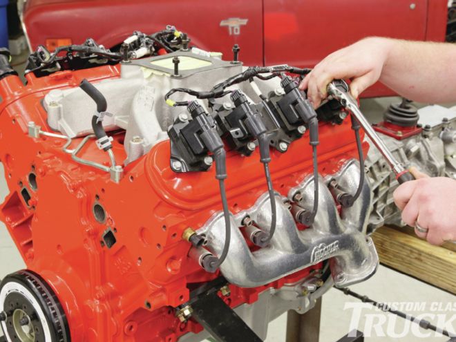
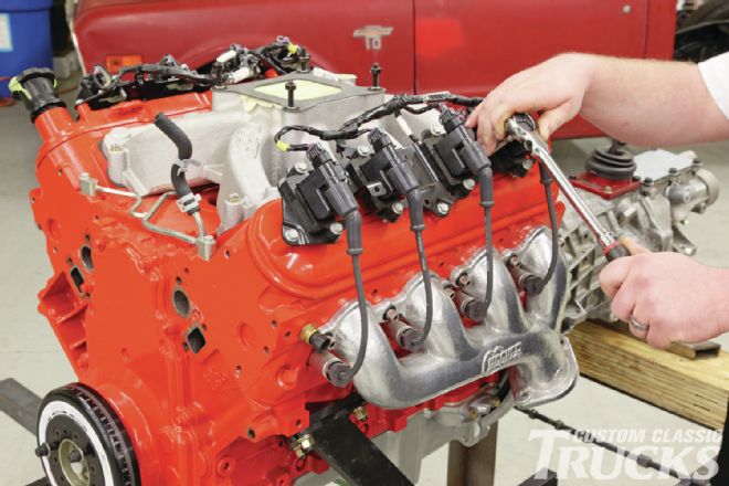 1. We start this process by removing the coil packs and the valve covers. This is accomplished with the use of 10mm and 8mm sockets.
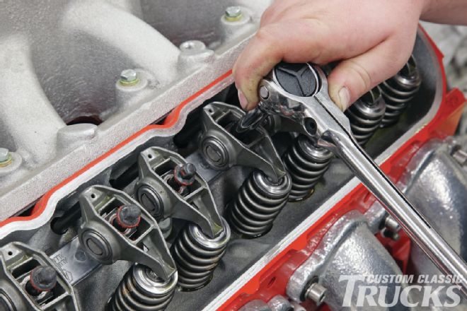 2. Next, remove the rocker arms and pedestal adapter plate. This is best done with a six-point 8mm socket. A 12-point socket if even slightly worn can round off the corners of the rocker bolts.
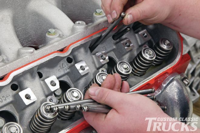 3. Once the rockers are gone, remove the stock pushrods as they will not be reused. With the bigger cam, Comp’s heavier-wall pushrods can be worth 4 to 6 horsepower at higher rpm.
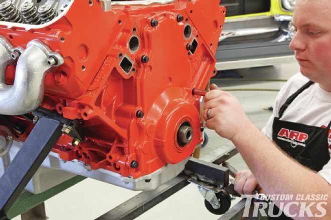
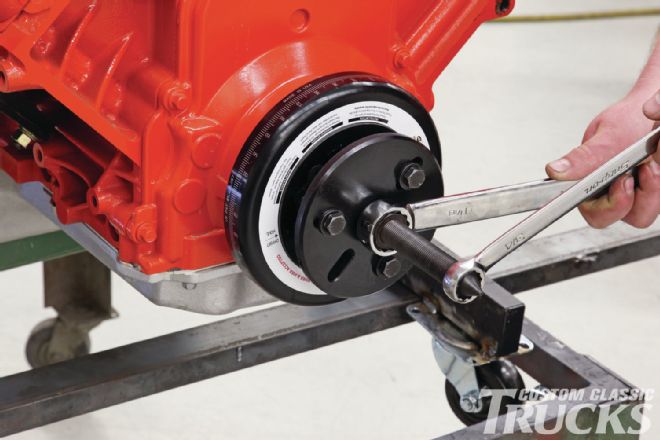 4. Using the correct puller we remove the damper from the crank. This particular damper is from ATI and uses a conventional style puller for removal. If a factory LS damper had been used there are several companies that make special pullers to remove them.
 5. With the damper removed the timing cover is the next part to be removed. Don’t forget the two bolts that come up through from the oil pan.
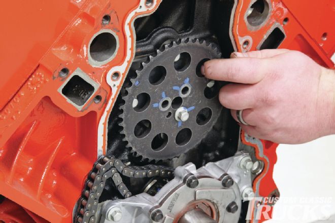
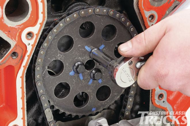
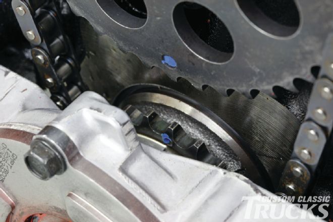 6. Before removing the top timing gear, make sure that you rotate the motor and align the dots on the top and bottom gears. This will ensure proper cam timing when the new one is installed. The blue dots are factory paint marks.
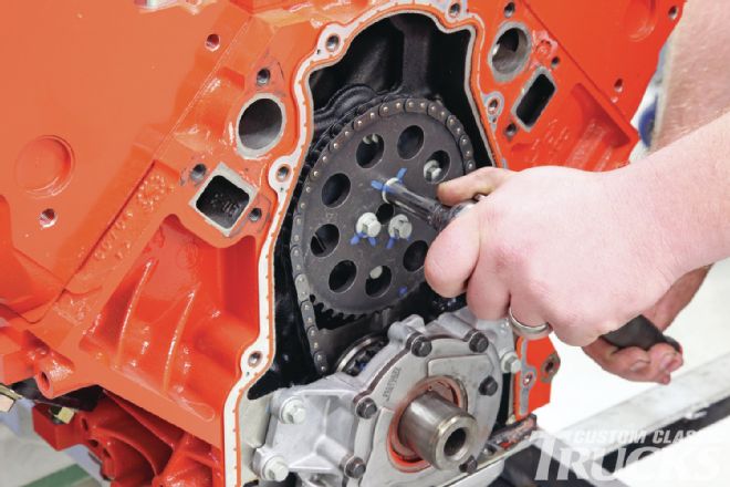 7. Unless you are changing the timing chain set, there is no reason to remove the oil pump from the motor. For now, the top timing gear is removed and the timing chain set to one side.
 8. Without pressure on the lifters, when the cam is rotated special keepers in the block will hold them up and out of the way, making cam removal and subsequent installation a breeze. Note that the gear has been reinstalled to ease turning the cam.
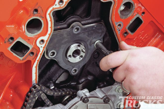 9. The cam retainer plate can now be removed and set aside. The bolts are discarded as we will be replacing them with new ones from ARP.
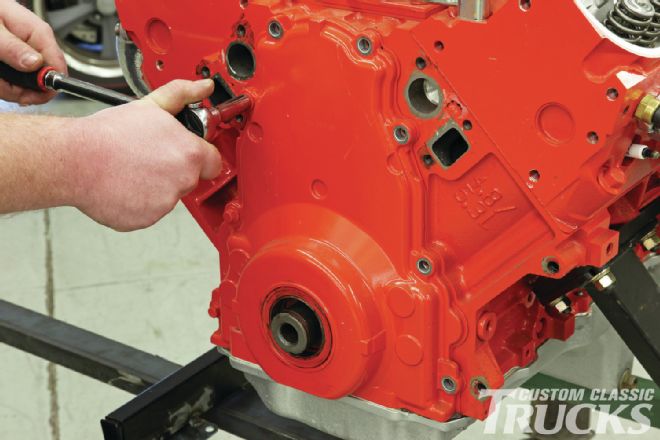
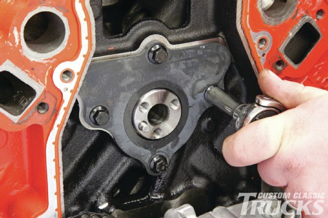
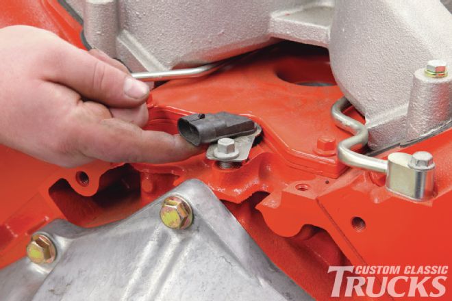 10. Our 5.3 is a 24X crank-triggered motor that has the cam sensor located at the back of the block. It’s a good idea to loosen the retainer bolt and lift the sensor up about ¼ inch to make sure it’s not damaged when removing or installing the cam.
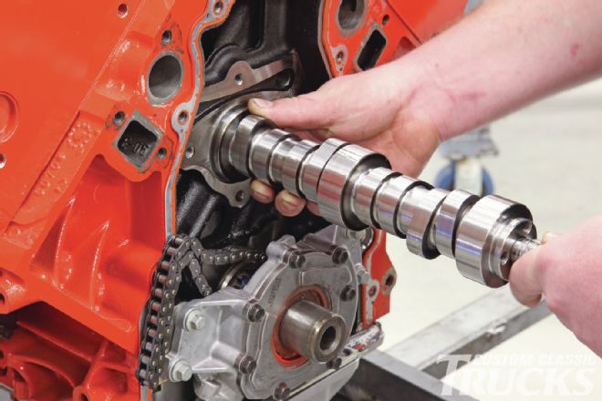 11. The old cam can now be carefully slid out of the motor. It may need to be rotated either direction to clear the lifters.
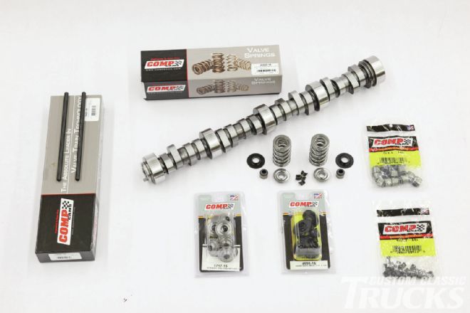 12. Here’s the valvetrain package Comp Cams put together for our LS327 based on the blower and head package we plan on using. The cam is a blower grind with 0.580-inch gross valve lift on the intake side and 0.586-inch on the exhaust. Duration at 0.050-inch lift is 220 degrees on the intake side and 228 degrees on the exhaust, with 114 degrees of lobe separation.
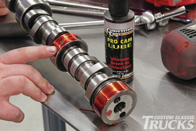 13. Before installing the new cam we coat all of the bearing journals with Comp Cams Pro Cam Lube.
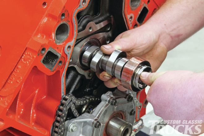 14. Care is taken to install the new cam so as not to damage the soft cam bearings. Once again it may be necessary to rotate the cam as it’s slid into place.
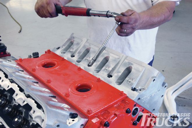
 15. The cam retainer plate is reinstalled using new ARP bolts that are torqued to spec.
 16. After rotating the cam to where the timing marks line up, we installed the top timing gear with ARP bolts and torqued them in place.
 17. Next, the front cover is installed; once again, don’t forget the two bolts that come up from the bottom through the oil pan.
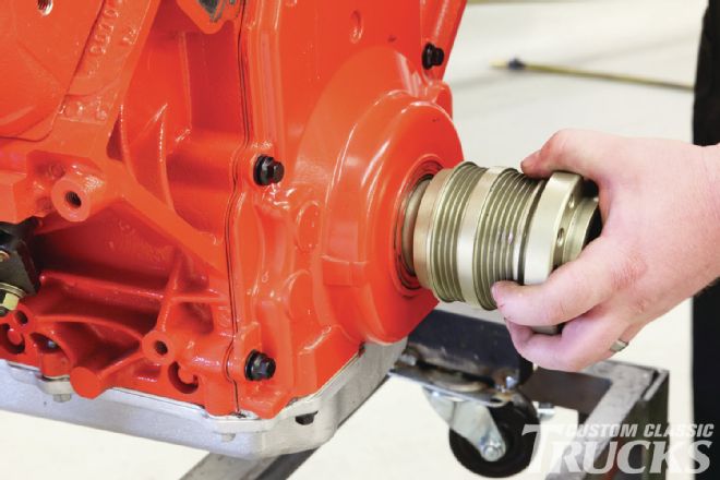 18. Because there are no ring dowels to locate the front cover, we use this old drive hub that has been honed for a slip fit on the crank snout to center the front seal. We then tighten the cover bolts in a star pattern to keep the seal centered on the crank.
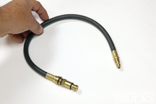 19. At this point if we were going to keep the stock heads on the motor, we would need to change the valvesprings to the ones recommended for the cam. To accomplish this task on the motor we use this hose from a compression tester and fill each cylinder one at a time with air, which holds the valves up in place.
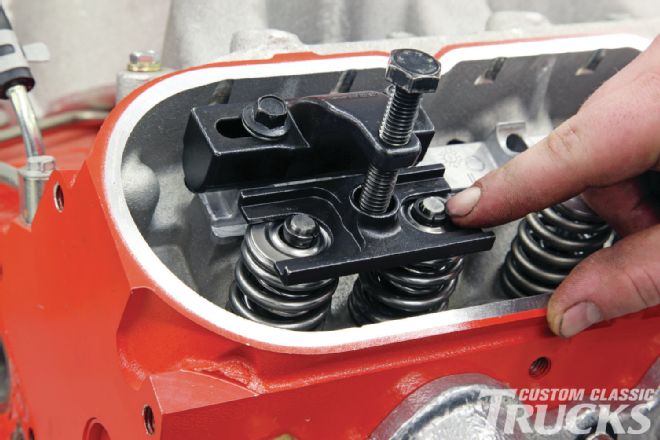 20. We’ve found that compressing the valvesprings and removing the keepers is much easier with this on-head spring compressor from Comp Cams (part number 5462). As you can see, it does both springs on one cylinder at the same time, so it’s a timesaver too!
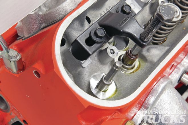 21. Remove the stock spring seat/valve seal combo to make room for the larger-diameter seat that fits the new springs.
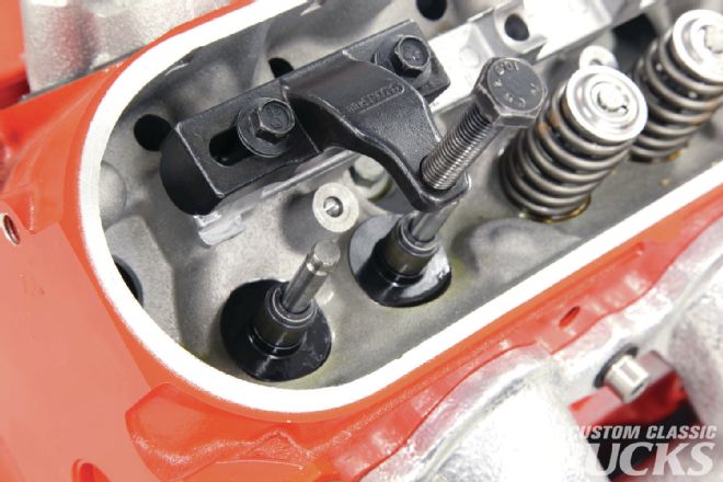 22. With the larger seats in place, the new valve seals are then installed.
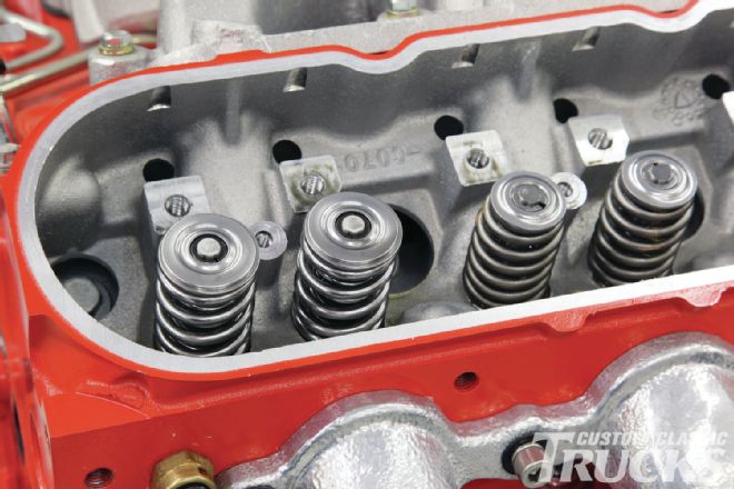 23. A quick check of installed height is done to ensure proper spring pressure. If the installed height is too tall, you could experience valve float due to lower spring pressure. If the installed height is too low, you could see premature lifter wear. With the first pair of springs changed (left), you get a great comparison of old versus new.
 24. The second part of our one-two punch is the cylinder head change, but there’s a step in between this simple R&R job.
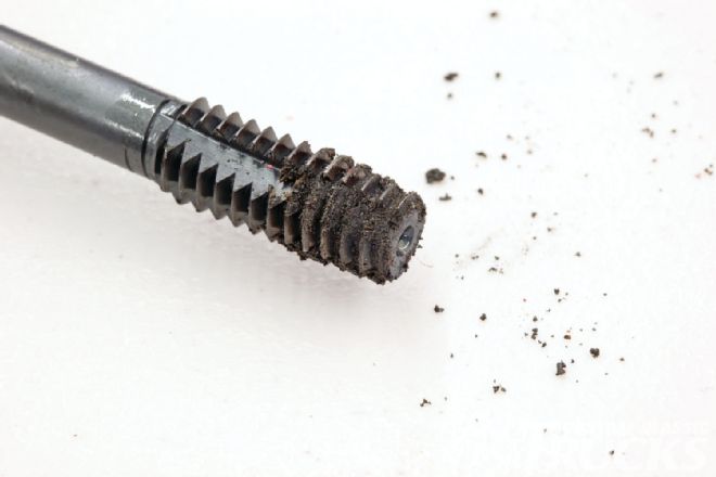 25. Just like with any vintage engine rebuild, it’s a good idea to chase the holes on an LS block when it comes to things like head swaps. For our block, we used a special ARP chaser tap that is slightly undersized to clean out the head boltholes. Unlike a normal tap, this chaser is intended to clean dirt and corrosion out of the threads while removing minimal thread material.
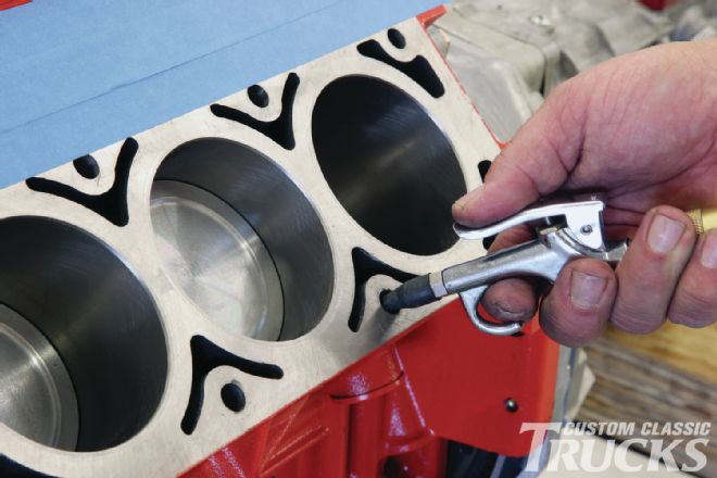 26. All LS engines use blind head boltholes, which means you must thoroughly clean them out after using the chaser. This is also a good idea any time a head is removed to ensure that no coolant or liquid is present at the bottom of the head bolthole as this could crack even an iron block because liquids don’t compress.
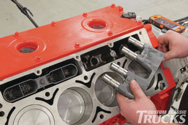 27. While the heads were off, we decided to go ahead and upgrade the lifters (since the only time you can access the lifters is with the heads removed) with Comp Cams’ performance hydraulic roller lifters.
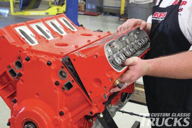
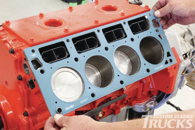 28. New heads demand new small-bore 5.3L MLS head gaskets from Fel-Pro. Notice there is a front and rear clearly marked on the gaskets to prevent an overheating situation from misaligned water passages.
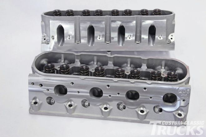 29. These are our CNC-ported Trick Flow 205cc intake port heads with a 58cc chamber and 2.00/1.575-inch valves courtesy of Summit Racing. Think these heads are great? At 0.500 lift TFS claims 299 cfm on the intake and 220 cfm on the exhaust. At 0.600-inch lift, the intake flow jumps to 316 cfm, with torque and horsepower ratings in the low to mid 400s.
 30. We also paid attention to the spring specs, and they meet the specs for our cam, so all we had to do was pull ’em out of the box, dust ’em off, and bolt ’em on.
 31. Early LS engines used two different-length head bolts. Oddly, this LS 327 is configured this way, so we ordered the appropriate head bolt kit from ARP, part number 134-3609. It’s important to note that because stock head bolts are a stretch-to-yield design, they should only be used once.
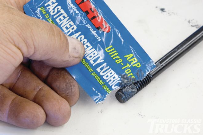
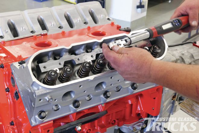 32. Torque specs are only good if you use ARP’s recommended fastener assembly lube. Because the head boltholes are blind, we don’t have to worry about water seepage past the head bolts. Be sure to put lube between the washer and the bolt head. Following GM’s torqueing sequence, we used three incremental passes of 40, 60, and 75 lb-ft of torque to fully compress the head gaskets.
 33. Don’t forget the top row of small 8mm bolts that are torqued to 22 lb-ft. Do these after the main head bolts are fully torqued.
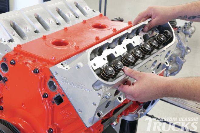
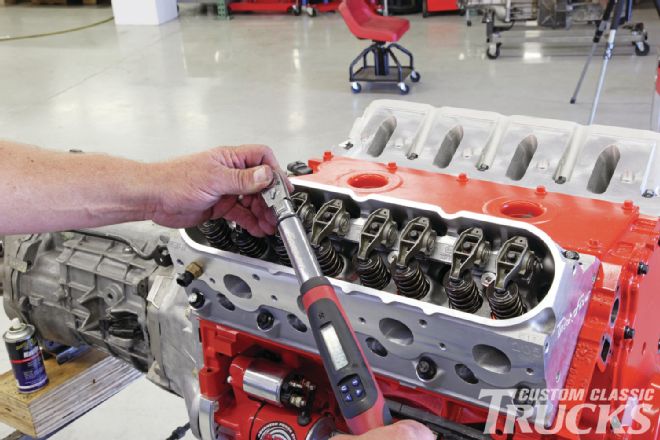 34. The TFS heads accept the stock rocker arms so it’s just a matter of installing the Comp thick-wall pushrods, aligning the rockers, and torqueing everything in place.
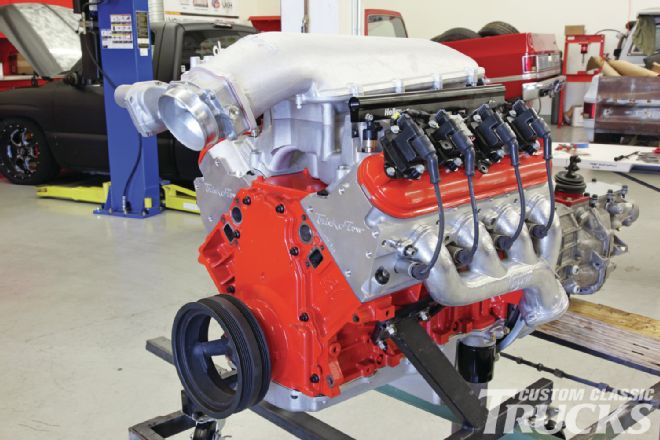 35. We will be using Holley’s new modular Mid-Rise EFI intake with a GM drive-by-wire throttle body that offers huge flow potential in both normally aspirated and supercharged applications. Although this manifold is a bit overkill for a small-displacement engine like this in normally aspirated mode, it’s perfectly suited for our blow-through supercharger setup, which we’ll cover here shortly. Stay tuned!