
Last month we explained how our pal Frank Wallic rebuilt a McCulloch supercharger for his roadster’s Flathead. We also stated that we were going to divulge the information we gleaned from our sources. Though the ’37 installation manual, parts listings, and brochures don’t account for a lot, they increase the amount of information currently circulating about McCulloch blowers by a log scale.
Before we start, bear in mind that McCulloch designations seem willy-nilly. The models usually designated 37 sometimes have 78 stamped on their tags instead—78 being the model designation for the 85-horse ’37 Fords. The year designations also seem to refer to the design date and not the vehicle model year. For example, we’ve seen models with 37 design hallmarks configured for ’35 and ’36 pump-in-head engines in McCulloch literature. And a brand designation doesn’t make a design model specific. For example, in the ’39 models only the ’39 Mercury unit fits the ’39 Ford DeLuxe. It just requires the 85-horse crank pulley for the smaller displacement.
The port adjacent to the oil-pressure sender port feeds the blower with a constant oil supply. The blowers drain by two ways, depending on the model. The ones that mount to Ford manifolds require an 11/16-inch-diameter hole on the driver side between the two leading bolts that mount the manifold to the block. A hose slips over the McCulloch drain, bends down 90 degrees, and presses into that hole. The blowers for the later models drain through a port in the supplied manifold.
McCulloch supplied 1/4-inch copper lines but oil from an unregulated supply will handily overwhelm the return port, fill up the gear case, and gush from the vent under the rotor. The “special fitting” that McCulloch indicated in the 1937 instructions likely has a restricted orifice. But flow metered by an orifice varies depending on oil viscosity, oil temperature, bearing tolerances, and engine speed. So it’s possible to set a level that’s perfect at idle or high speed but not perfect at idle and high speed.
Apparently McCulloch understood this because in the ’39 parts sheet it lists what it refers to as an oil-relief valve, which consists of a plunger, spring, and nut. The name and those parts’ descriptions indicate that the valve bypassed (or relieved) excess oil to the crankcase. Once set, such a valve would better maintain a specific oil level within the blower regardless of engine speed, viscosity, and so on. Unfortunately, small bypass valves are expensive.
Heating the intake air is a good idea on a road-going engine with a wet intake manifold (one that transfers fuel as well as air). Most of us are aware of one benefit: a warm manifold prevents a carburetor from icing. But warm intake air also keeps fuel suspended as a finely atomized mist that more readily burns. It also improves combustion efficiency by accelerating the combustion rate.
McCulloch endowed all but its earliest superchargers with a means to heat the rotor housing. The rotor housing offered in 1937 looks like a hamburger bun with coolant ports on the side. The passenger port connects to a nipple threaded into a bung just below the water neck in the head. The driver’s port connects to a nipple in the upper radiator hose near the radiator or in the radiator itself. That plumbing gives the coolant a low-resistance path around the thermostats.
McCulloch introduced its own manifold and redesigned the rotor housing in 1938. That design plumbs the hot exhaust gases from the crossover ports to a thermostatic-controlled intermediate housing below the blower outlet. The gases then go through the rotor housing.
In 1939 McCulloch reverted back to coolant to heat the rotor housing. The company produced two versions. A Ford-badged one fits all Fords to 1938, ’39 standards, and ’39 pickups. A Mercury-badged one fits the ’39 Mercury and the ’39 Ford DeLuxe passenger cars.
In the Ford-badged models a stubby radiator hose routes all of the coolant from the driver-side head to a neck on an intermediate housing that fits between the manifold and blower. The coolant ascends into the rotor housing and exits to the radiator by a large port cast in the top of the driver-side rotor housing. The high outlet means the Ford-marked blower won’t fit the ’39 Mercury or Ford DeLuxe. The passenger radiator hose fits as Ford intended.
The Mercury-badged design is a bit more sophisticated. The passenger head’s water outlet feeds one leg of a two-branch iron elbow. That feeds one side of an aluminum intermediate housing between the manifold and rotor housing. The other side of that intermediate housing returns the coolant to the second leg of that two-branch elbow, which connects to the upper radiator hose. To the best of our knowledge the thermostat mounts between the second elbow and the radiator hose.
We say that because the thermostat can’t mount where Ford intended it, on the head’s water outlet. A stem descends down into the passenger head water jacket. This stem feeds coolant to a fitting cast into the passenger-side rotor housing. According to the parts list, the fitting on the driver-side rotor housing feeds the coolant to a fitting threaded into a hole drilled in the driver-side water pump inlet. For what it’s worth, this is a potentially good return path for the earlier models to follow as the pressure is lower there.
Yes, we are aware that tuners go to great lengths to cool the intake charge in other blown applications but that’s generally an advantage at boost pressures greater than 8 psi. You’d be lucky to achieve half of that with a McCulloch blower, so take advantage of the other properties that a heated rotor housing offers. It does improve performance.
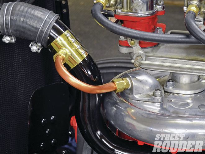
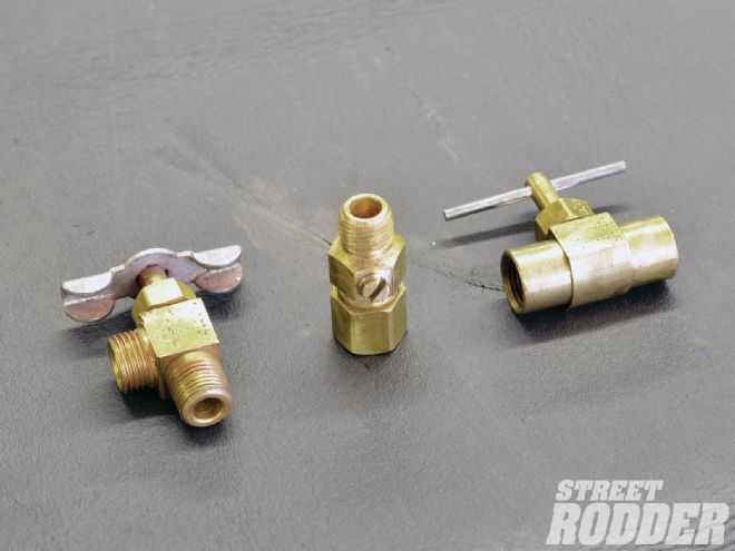 1| In lieu of McCulloch’s “special fitting” Wallic used a 1/4-inch industrial adjustable-flow brass needle valve to regulate oil flow. About the only requirement is that they seal at the adjuster shaft.
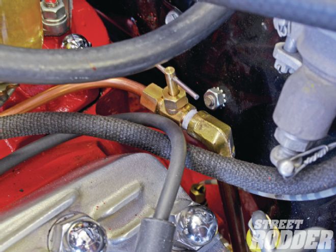 2| The blower oil-feed tube taps into the port that Ford drilled for the cam feed. It ordinarily has a plug in it. He mounted the needle valve near its entrance.
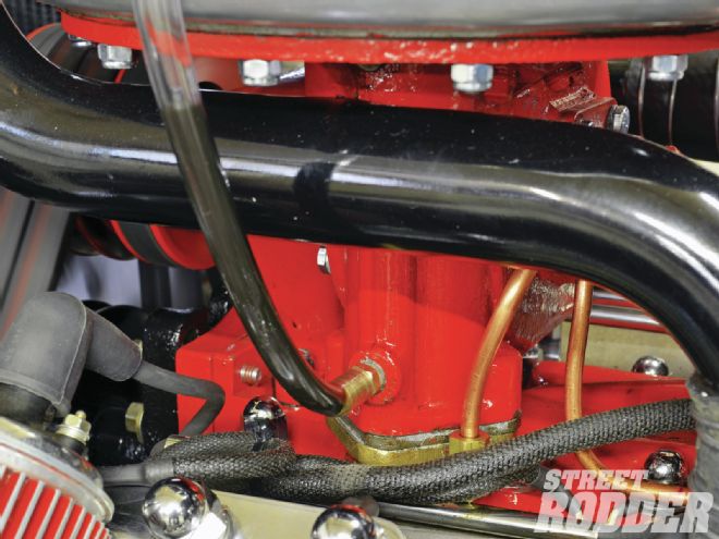
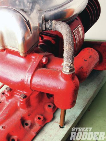
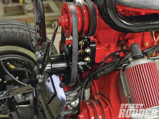
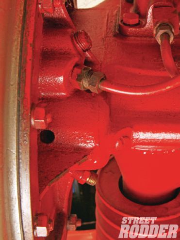
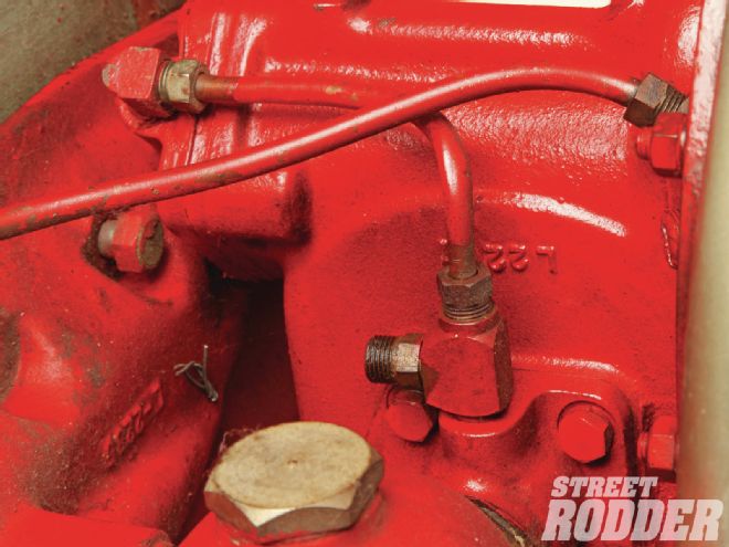 3| This is how McCulloch oriented the oil line fittings, the tee mounting directly to the rear bearing retainer and the secondary line feeding the lower bearing retainer. The oil line feeds the tee indicated by the arrow.
 4| Wallic made this clever sight glass of sorts to check the oil level inside the blower. It’s just a brass fitting that threads into an unused boss near the bottom of the blower housing with clear vinyl tubing pushed over its barb. This level indicates the oil level at idle with the oil-line valve just barely open.
 5| The level in the last photo may be a bit too low but here’s the oil level with the same valve setting after Wallic throttled the engine up to a few thousand rpm. This reveals the shortcoming of setting flow by restricting the line: the level varies with speed.
 6| This shows the oil level when Wallic opened the needle valve another turn or so. Bear in mind that this is just at an idle. He had to temporarily plug the breather hole as oil would’ve gushed from it otherwise.
 7| A bypass valve would better maintain a more consistent level regardless of engine speed but small ones usually cost too much to experiment with. Someone tapped the breather port on his blower so Wallic rigged up a line that comes out of it.
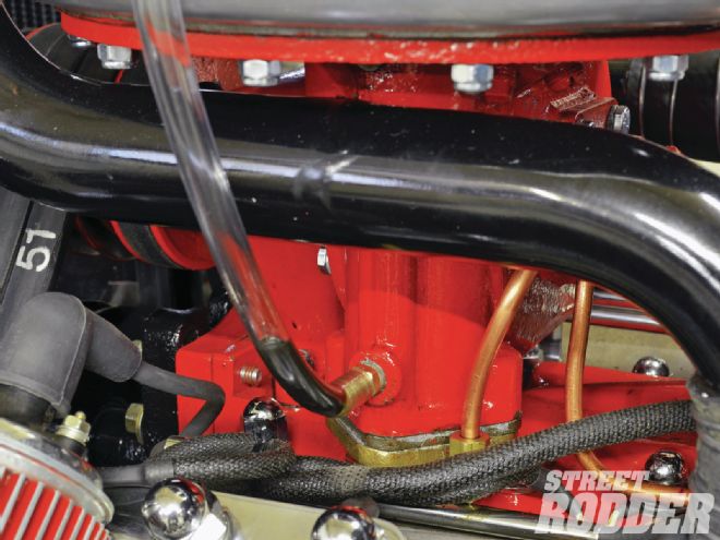
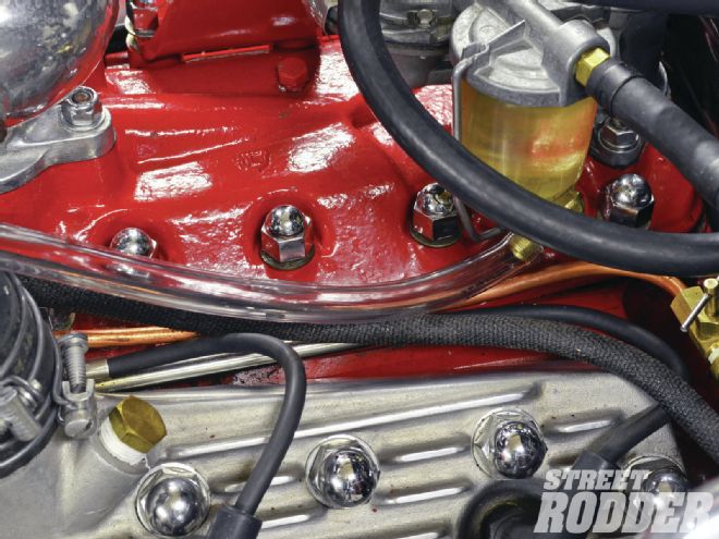 8| Wallic plumbed the return line to a port in the manifold that accesses the lifter valley shown here in mock-up with vinyl tubing. If you take this route then ensure that you don’t return oil into one of the manifold runners for obvious reasons. The return line doesn’t interfere with the breather function but it lets excess oil return to the crankcase.
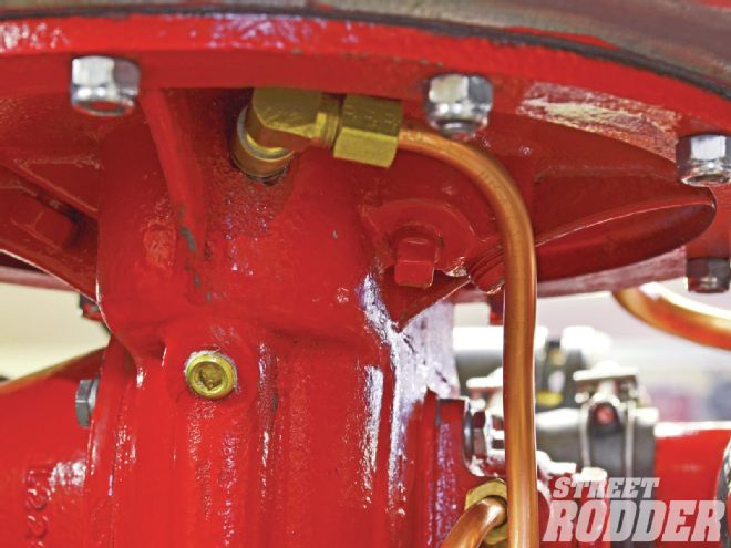
 9| On the Mercury-badged models a short hose connects the head’s water outlet to the elbow in the foreground. The stem descending from it explains why the thermostat moves to the elbow that points away from us in this photo. The hose connects that stem to the passenger nipple in the rotor housing.
 10| Wallic followed the ’37 instructions and plumbed the driver-side rotor housing fitting to the driver’s radiator hose but the ’39 parts list indicates a tapped driver-side water pump housing. Either way will work so long as one line gets the positive pressure from the head side of the thermostat and the other side gets the negative pressure from the radiator side.
McCulloch made its own crank and water pump pulleys to drive its superchargers with three belts. In 1939 it offered three crank pulleys: one for short cranks to 1938, a second for ’39-and-later Ford passenger cars and light trucks, and a third for ’39-and-later Ford heavy trucks and Mercurys. Darr’s literature shows two blower ratios: 1:6 for 221ci Ford engines and 1:6.6 for heavy-truck/Mercury 239ci engines.
At least in 1939 McCulloch offered two water-pump pulley types: one bored to fit 5/8-inch-diameter shafts and another bushed to fit 1/2-inch shafts (1937 and 1938). The ’35 and ’36 pulleys are exclusive to those years.
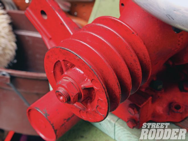
Until 1938 all McCulloch-driven pulleys have three sheaves and accommodate the cooling fan. Those models drive the generator from a separate pulley pinned to the driveshaft where it protrudes from the rear bearing retainer.
In 1939 McCulloch eliminated the separate generator pulley, relocated the generator forward on the driver head, and drove it from the rearmost sheave on a four-sheave driveshaft pulley. It offered two versions of that pulley. One had a cooling-fan mount for all Fords to 1938, ’39 Ford trucks, and ’39 standard Ford cars. The driveshaft pulleys for the ’39 Mercury, ’39 Ford DeLuxe, and all ’40 cars and trucks lacked fan provisions as the crank pulley on these cars drove the fan.
As rare as they are, McCulloch blowers outnumber the pulleys. So many enthusiasts like Wallic improvise with two-sheave crank and water-pump pulleys from ’37-41 heavy trucks.
Multi-belt drives present a unique problem: their lengths must match. That’s nearly impossible to achieve but Wallic discovered the solution: banded V-belts.
Banded belts are flat belts made of multiple conventional V-belts. Simply order a belt with the number of V-belts at the length the application requires and cut the belts apart. Voilà, multiple belts that match exactly!
The superchargers that McCulloch produced until 1937 fit the stock Ford intake manifold. The supercharger case is unique unto itself. It mounts to the carburetor pad and the generator boss.
Some very early product literature of the kits intended for pump-in-head engines don’t acknowledge belt tensioners but photos reveal what looks like a slot in the bracket that mounts to the generator boss on the Ford manifolds. That suggests that the whole blower assembly moved vertically to set belt tension.
That of course raises an issue with the space between the rotor housing and the intake manifold; however, the installation paperwork for the ’37 blower explains the role that fiber shims play to take up the gap between the rotor housing and the intake manifold. We know for sure that the ’37 blower didn’t move to set belt tension. Instead the ’37 models (even the ones made that year for the earlier pump-in-head engines) used a belt tensioner that bolted to the timing cover and pressed against the inside of the belts. So the shims existed on those exclusively to compensate for manifold manufacturing variances.
McCulloch delivered blowers with its own manifolds from 1938 onward. That model features an integrated belt tensioner and employs exhaust from the crossover ports to heat an intermediate manifold between the blower and Ford manifold and the rotor housing. It eliminated the exhaust-heat provision in 1939 when it revised the rotor housing to once again use coolant for heat.
McCulloch deemed the stock single-exhaust system inadequate and recommended giving the left exhaust manifold its own pipe and muffler. In fact the company offered a kit to do just that for $14.95 (a bargain even when adjusted for inflation: $249.70).
Supercharging accelerates combustion rate therefore a supercharged engine doesn’t need/can’t use as much spark advance as a naturally aspirated engine. At full advance the stock ignition sparked each cylinder at about 22 degrees before top dead center. McCulloch recommended limiting total advance to 16 degrees BTDC and setting final timing on a car-by-car basis.
According to Darr’s service-data sheets, McCulloch offered special distributor springs. Presumably these springs were stiffer to cause the brake to engage and retard the timing and stave off detonation at lower manifold pressures. McCulloch deemed the remainder of the ignition system, spark plugs included, adequate for supercharging.
McCulloch referred only to the 48-series Stromberg carburetor in the ’37 installation manual. It recommended 47 jets at sea level and 45s at high altitude for the 48. It made no other distinctions for the remainder of the fuel system.
Wallic says he likes the twin 97s on the Speed Gems’ slingshot adapter for their eye candy but admits they’re tough to package (these blowers perch carburetors pretty high as it is). Truth be told an early McCulloch probably can’t use much more than half of what two carburetors can supply.
Blowers like these have a fixed capacity, in this case enough to support about 120-150 hp regardless of an engine’s size or tune. A larger, single carburetor (think luxury cars from the ’40s) can flow enough to support that output. It may require an adapter but it needn’t be thick.
Intake charges forced past intake valves at greater velocity tend to overwhelm the valve springs. Supercharging also generally lets the engine operate at speeds faster than stock. For that reason McCulloch recommended valvesprings at least 25 percent stiffer than stock.
 11| Since the Mercury and ’39 Ford DeLuxe drove the fan from the crank the driveshaft pulleys from the Mercury-badged blowers lack fan mounts. They’re flat like this but they can be swapped for the Ford-specific pulleys with fan mounts.
 12| McCulloch designed the ’39 generator bracket to mount to a pattern that’s oddly identical to the Flathead generator mount pattern on the manifold. That pattern is the same as the pattern for the ’42-48 car and ’48-and-later truck fan idler bracket.
 13| Wallic exploited that feature by using such a fan assembly. Of course he had to have a new fan hub made to align the belt with the forward pulley sheave. The crank drives the middle sheaves and the rear sheave drives the generator. In the original design the third belt would drive this sheave.
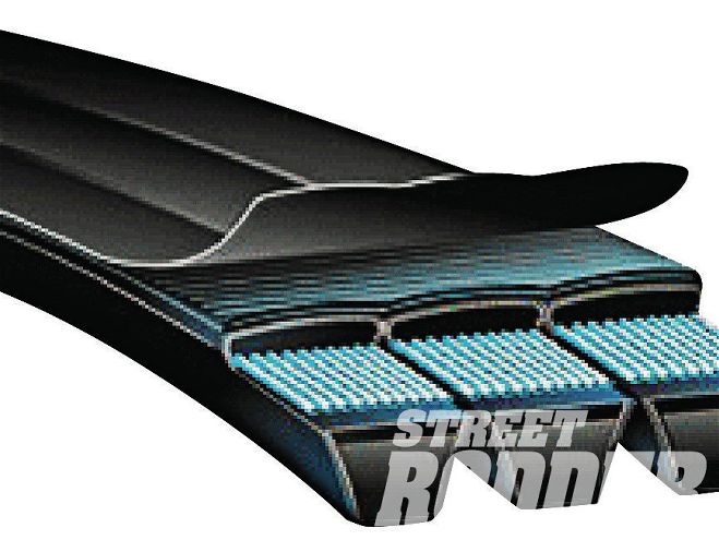 14| A banded V-belt is merely a number of V-belts ganged together. All of the belt lengths match as they’re formed as one. That makes them ideal for multiple-belt drive systems.
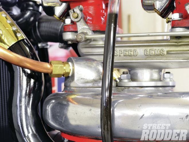
 15| McCulloch integrated the belt tensioner with the manifold starting on one of the ’38 models. It and the ’39 tensioner’s wheel exert pressure on the flat backside of the belts.
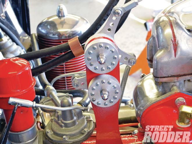 16| The elevated carburetor mounting creates a bit of an issue and the Y adapter makes a huge issue. Wallic made this elegant contraption from bellcrank bearings, spherical rod ends, and aluminum plate stock. The second bellcrank reverses the first crank’s direction.
 17| Several vacuum ports protrude at an angle from underneath the blower housing. The one in the foreground with the pipe on it drives the windshield wipers. The one in the background without the pipe advances the ignition advance.
Frank Wallic
[email protected]