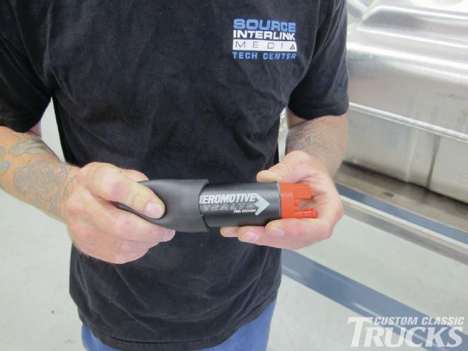
For many CUSTOM CLASSIC TRUCK aficionados, building that dream ride comes in increments. We constantly hear from those who are running a carbureted engine, but plan on adding fuel injection at some point. Then there are those who want to update their truck’s fuel system by moving the tank from inside the cab to under the bed. Then there are those who want to ditch the mechanical fuel pump, but don’t want the noise associated with an inline electric fuel pump. For all those issues and more, there is a slick solution—Aeromotive’s Phantom 340 Stealth Fuel System.
Aeromotive’s in-tank pump has a host of advantages, among them is with the pump submerged in fuel it runs cooler, which translates into longer life and it’s a whole bunch quieter to boot. Suitable for carbureted or fuel-injected applications, it will support up to 700 horsepower with an EFI and 1,000 horses in carbureted supercharged applications—of course it will feed a mild crate motor just as effectively.
Aeromotive’s Phantom Stealth system can be installed in virtually any fuel tank with a depth of 5.5 to 11 inches (a special baffle/basket assembly is available for deeper tanks). Recently Jason Scudellari installed an Aeromotive system in a 1967-72 Blazer gas tank from Brothers. This particular tank is going in a Suburban; however, it is also a popular replacement for the in-cab tanks found in many C10 pickups. Take a look at how it’s done; it may be the cure for your gas pains.
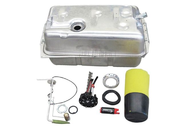 1. All the ingredients for a first-class fuel system. Along with the Aeromotive system we used a new tank from Brothers (part number BSGT069), it measures 26 inches wide, 13 deep, 17 long, and holds 21 gallons. The stock gas gauge sending unit (part number GTS6972) is 0 to 90 ohms for original gas gauges (the original pickup won’t be used with the in-tank pump).
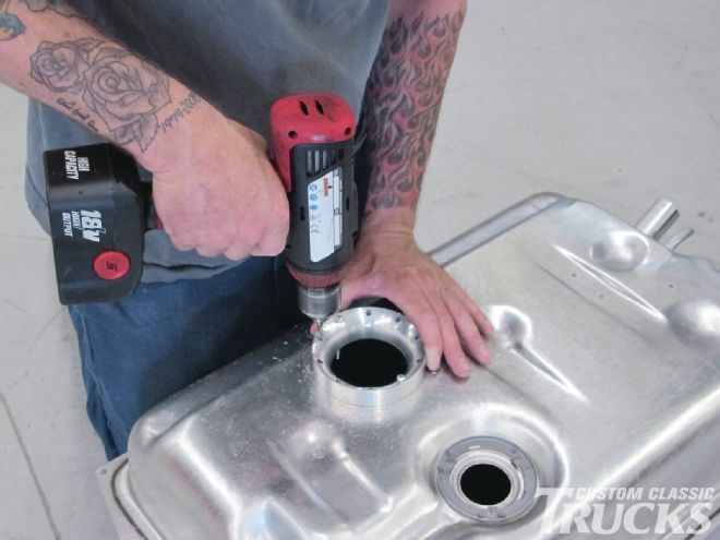
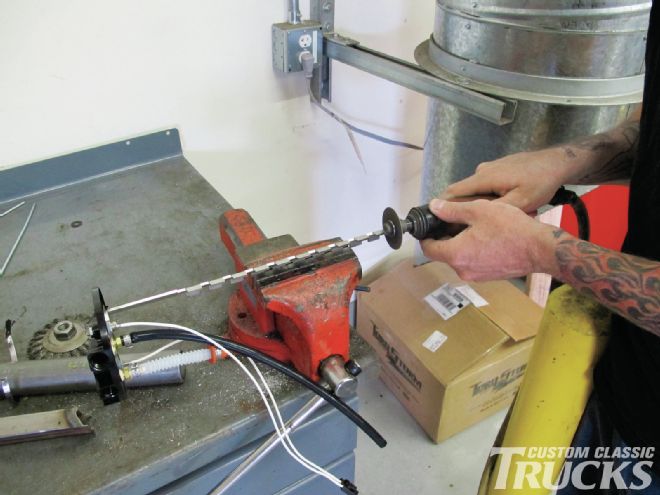
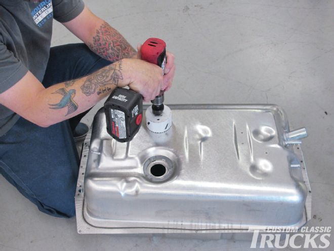 2. The first step to installing the pump and pickup is making an opening with a hole saw.
 3. With the hole cut this drill guide is put in place; it has a lip to register in the newly made hole. You’ll see why the guide has a rounded edge shortly.
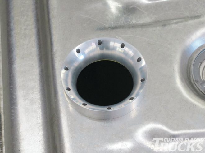
 4. After drilling a pair of holes, two of the included screws are used to hold the guide firmly in place while the remaining holes are drilled.
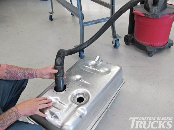 5. Once the modifications are complete, the tank has to be thoroughly cleaned.
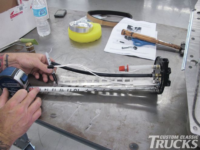
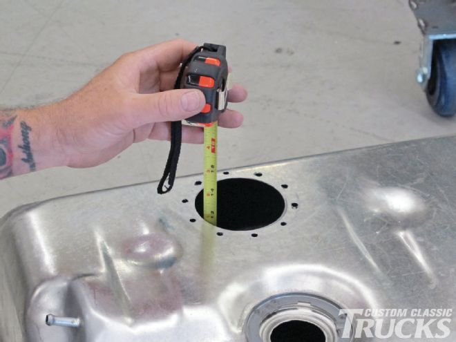 6. With the tank emptied of debris, Jason measured the depth of the tank so the pump bracket and the baffle/basket assembly can be cut to the proper length.
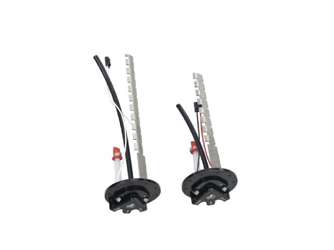
 7. These are baffle/basket assemblies (left is extra length version, right is standard). The basket (at the bottom) acts as a sump for the pump.
 8. Here’s a pair of pump mounts with pickup tubes attached; the short black tube is the fuel return, while the pigtail wiring harness attaches to the fuel pump. Connections are provided for fuel pickup, return, and vent.
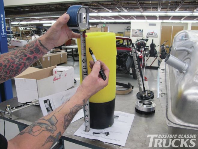 9. With the depth of the tank known the foam baffle is cut to length.
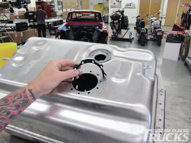 10. This ingenious little device is the split ring that has studs to secure the pump bracket/pickup assembly to the tank.
 11. The split in the ring allows it to fit through the opening—good thinking on Aeromotive’s part.
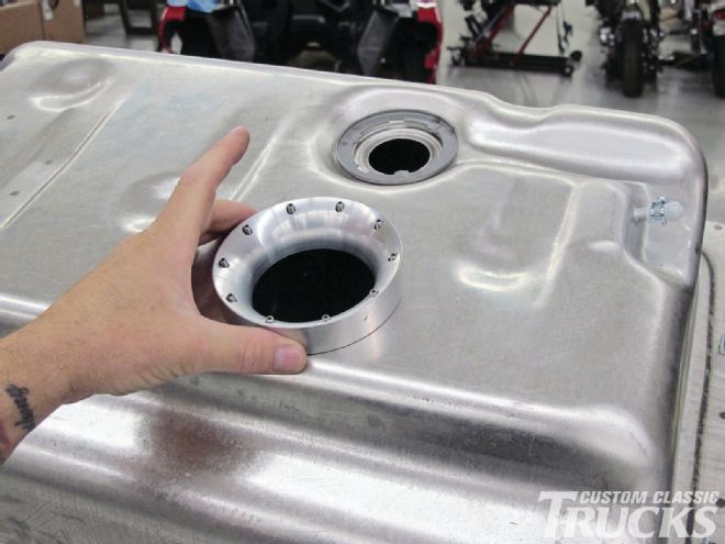 12. With the studs protruding from the tank, the drill guide is put back in place.
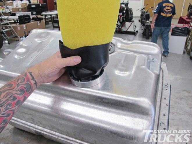 13. Now the reason for the drill guide’s rounded opening—it makes installing the baffle/basket assembly easy and without damage.
 14. Using the measurements taken earlier, the pump mounting bracket is marked to be cut to the proper length.
 15. Jason used a cut-off wheel to shorten the mounting bracket; he then made sure there were no burrs that could drop off later.
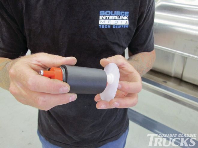
 16. The Aeromotive 340 fuel pump is slipped into a foam sleeve...
 17. …and then the pickup is attached to the inlet.
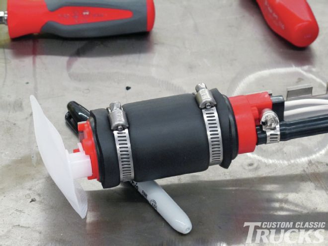 18. A pair of hose clamps secure the pump and pickup assembly to the mounting bracket.
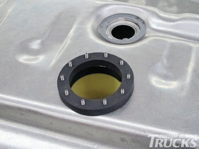 19. To prevent seepage, a thick gasket is put in place over the studs.
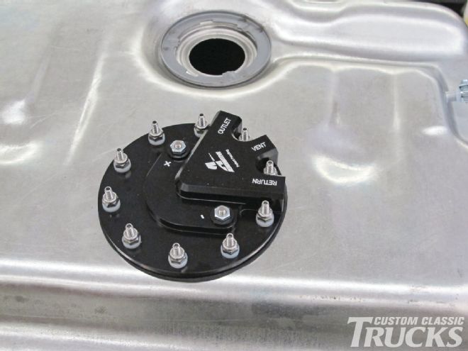 20. The pump and pickup are simply dropped in place and secured with the included lock nuts. The outlet, vent, and return connections are ORB-06. Plus and minus connections are power and ground for the pump.
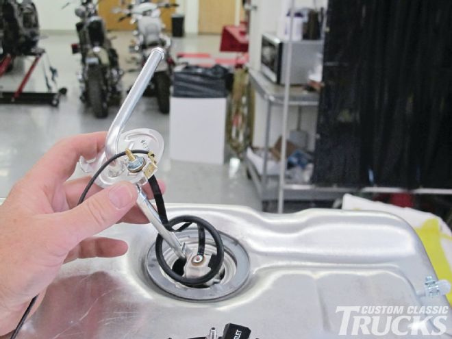 21. A stock pickup/fuel level sender was installed to provide a signal to the gas gauge; however, the stock pickup tube won’t be used.