
When HPP left Racekrafters' shop the last time, The Mule performed quite admirably with the out-of-the-box Edelbrock cylinder heads installed. It produced 502.8 hp and 570.7 lb-ft of torque.
As always, it did nothing wrong but make power like a freight train. But as stated in the previous installment of this series, all of us were a little dumbfounded by the stroked and bored 455's reluctance to spin higher in rpm and still move the dyno needle.
Going into the test, we all believed that the better-flowing and larger intake runner Edelbrock D-port heads would not only give us power, but also expand the engine speed range.
By all accounts, we are nit-picking though. Any Pontiac enthusiast who would bolt on a set of these heads in place of stock 6X castings would think that a nitrous bottle was mysteriously added in the trunk. The Mule, however, enjoyed fully worked 6X head castings from the skilled hands of Corey Porter under the tutelage of Bob Wise and his airflow expertise. So our expectations were jaded going into the original test, since our jumping off point was higher than most. After discussing the results, we decided to swap in a more aggressive cam and matching valvesprings to see what would happen.
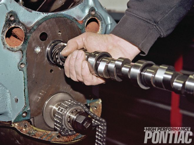 Craig Wise installs a more aggressive Comp Cams hydraulic roller cam for testing in The Mule. This is not a how-to-swap-a-cam story, so just a few highlights of the swap will be covered here.
When RaceKrafters designed the engine combination that became our Mule, the goal was for a street-friendly, drivable, and octane-tolerant powerplant. Over the past year, we have proven time and again that every goal was not only met but also exceeded.
As with any engine and especially a true Pontiac, the camshaft design is going to be paramount in the personality of the mill. The camshaft can make or break the engine combination. With this established, RaceKrafters chose the popular Comp Cams hydraulic roller (PN 51-423-9). This cam has duration at 0.050-inch lift of 224/230 degrees, 0.552/0.561 lift, and a lobe separation of 110 degrees.
No one could argue with the results it provided. But Comp Cams part number 51-433-9 offered both more duration (236/242 degrees) and lift (0.572/0.594) while still working with the same basic valve events. In many ways, one could think of it as our original cam placed on a copy machine and blown up in size. There are other subtle differences in the two grinds once the cam cards are reviewed.
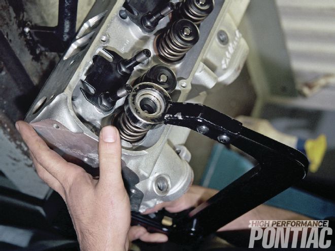
 1 The new higher-pressure Comp Cams valvesprings used the same steel seat that the others did.
If you recall as the author, I believed that the valve opening and closing points would possibly need to be modified to work better with the Edelbrock cylinder heads. And when a cam profile is tweaked it is almost impossible to alter the duration while not impacting some other aspects of the grind. This was the case with our two Comp Cams bumpsticks.
The original cam (PN 51-423-9) had the intake valve open at 6 degrees BTDC and close at 38 degrees ABDC, while the exhaust valve opened at 49 degrees BBDC and closed 1 degree ATDC. In contrast, the new cam (PN 51-433-9) opened the intake valve at 12 degrees BTDC and closed it at 44 degrees ABDC. The exhaust lobe opened the valve at 55 degrees BBDC and closed it at 7 degrees ATDC.
From a theoretical standpoint, the intake valve would open when the piston is at TDC, beginning its intake stroke (not BTDC). It would then close when the piston reached BDC, not ABDC, so no intake mixture could escape when the piston started upward. The exhaust valve would open at BDC, after the expansion or power stroke (not BBDC), and close at TDC (not ATDC), after the exhaust stroke.
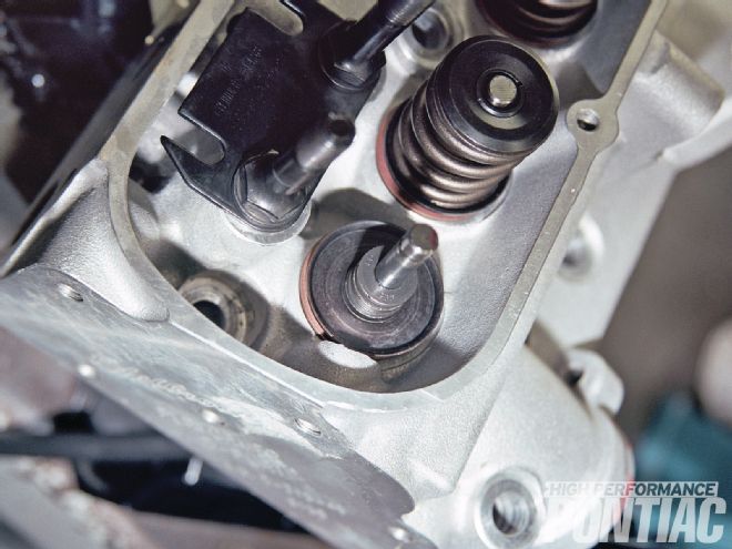
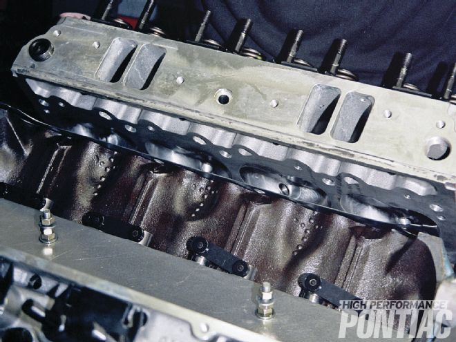
 2 To start the cam swap, Corey Porter removed the Edelbrock heads and checked the open and closed pressure on the Comp valvesprings before installing them. The specifications are in the text.
An engine with this cam timing, however, would not be very efficient for a number of reasons.
Intake mixture and valvetrain parts have inertia. This means that they do not like to get moving, and once in motion are difficult to slow down, stop, or have change direction. Due to this, the valve events are started earlier in the cycle, as depicted in the Comp Cams cam specs.
The intake valve gets a head start and opens before the piston begins the intake stroke, and then it will open further once the stroke begins. The intake valve does not close until the piston passes BDC because the charge can still fill the bore due to inertia. The same principal applies to the exhaust valve. It opens before the piston reaches BDC and closes after the piston reaches TDC. Thus, the valves are opening sooner and closing later, all while staying open longer and being lifted slightly higher with the new cam grind.
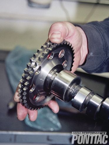
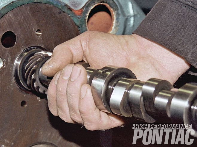
 3 Craig removed the Comp XR276HR cam and prepared the new XR288HR for installation. It did not come with a key, but a big-block Chevy crankshaft key works fine on a Pontiac cam.
The lobe lift on the original cam is 0.3350/0.3400 inch, intake and exhaust, respectively. In the same order, the new cam provided 0.3470/0.3600 inch lift. The total valve lift is these values multiplied by the rocker ratio employed.
The following is a comparison of the different valvesprings we used. The heads are still virgin but the more aggressive camshaft and valvesprings are now in place.
6X Springs Edelbrock Springs Comp Cams Springs Installed height (in.) 1.685 1.780 1.710 Open (pounds) 275 275 305 Closed (pounds) 130 110 105
Since the entire premise of The Mule is research and education, HPP felt that this would be a prime opportunity to provide our readers with some camshaft theory via a brief tutorial.
The function of a cam is to smoothly open and close the valves as far and as fast as possible. The smoothness of the profile is paramount in deciding the life expectancy of the valvetrain and the components. This is the main difference between a race and street cam. A race design will open the valve in fewer degrees of rotation but will be very hard on the valvetrain parts. The closing force for the valve is applied by the valvespring but dynamic concerns for valve lift need to be ground into the cam to control the speed at which the valve opens.
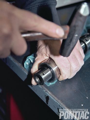
 4 Craig trial-fit the gear to the camshaft and keyway before installing it in the block. Everything mated perfectly with our engine.
Modern cam profiles are a computer-generated balance of competing concerns for engine performance, emissions production, specific fuel consumption, valvetrain life, and cost. A cam consists of a base-circle, opening and closing ramps, and polynomial generated curves for the opening and closing main events. The words opening and closing are derived from the direction of the valve travel.
These terms are common to cam design.
Ramp: The portion of the cam lobe event from zero lift (base circle) to the defined opening or closing point.
Base circle radius: The portion of the cam contour at zero lift (valves closed).
Flank: The section of the cam lobes between the ramp and the nose radius.
Nose radius: The radius that is tangent to the flank and the maximum lift point. Also, the instantaneous radius at the maximum lift point of the nose of the cam.
Inflection point: The point on the lift curve where the lifter instantaneously changes direction.
Main event: The portion of the cam lobe profile from the ramp to the nose. There are two main events: one each for the opening and closing halves of the profile.
Velocity: The rate at which position changes. In most instances it is expressed in terms of distance versus time (mph, feet per second, etc.). When dealing with camshafts, time is replaced by degrees of camshaft rotation. This allows the study of camshaft profiles independent of engine speed.
Acceleration: The rate at which velocity changes. It is expressed when discussing a camshaft as inch/degree or thousandths/degree.
Jerk: How fast the acceleration changes. It is expressed in units of inch/degrees.
Duration: The amount of time in crankshaft rotational degrees that it takes for the lifter to travel from a specified lift point on the opening side of the lobe to the same lift point on the closing side. Unless you know the specified lift point, a duration number does not tell you much. Unfortunately, this is often omitted and there are different standards in use.
 5 Since the cam is a roller design and the engine will be primed before starting, no cam lube is required. A flat tappet cam would require cam lubricant though.
The following are the specifications:
Old General Motor's specification 0.020-inch lifter travel Aftermarket 0.050-inch lifter travel Advertised 0.004 inch lifter travel SAE 0.006-inch lifter travel
Since the aftermarket value of 0.050-inch lifter travel is the most common to our readership, it will be used to explain duration.
If a cam is rated at 236 degrees at 0.050 inch, that means it requires 236 degrees of crankshaft rotation for the cam to move the lifter from 0.050 inch lift to a fully open valve and back down to 0.050 inch lift. The advertised duration is determined at 0.004-inch lift. It will always be longer than the 0.050-inch duration.
Now let us consider two cams with the identical 0.050-inch duration but different advertised duration. This would imply that the ramp on one cam is steeper (more commonly, quicker) than the other, since the amount of travel needed to drop to 0.004-inch lifter displacement varies. Once you study this, you will conclude the cam with the lower numerical advertised duration and a similar-at-0.050-inch value is ground with a quicker opening. This is established by the fact that it required less rotation of the crankshaft to bring the lifter the additional 0.046 inch (on each side of the lobe) to the advertised standard.
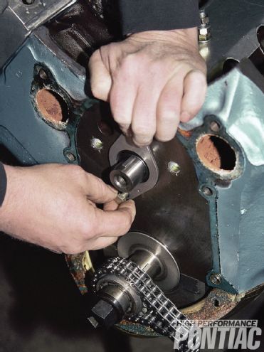 6 With the thrust plate installed, the new cam was ready to be buttoned up and end play confirmed.
Lobe centerline: This represents an imaginary line referenced from the true center of the base circle out to the end of each lobe, in crankshaft rotational degrees. Intake centerline values are found in the crankshaft's rotation after top dead center (ATDC), while exhaust centerlines are found at travel before top dead center (BTDC). Lobe centerlines are commonly thought to be the actual mid-point of the flank, and are usually close to that but different ramps on the opening and closing sides may change that reading. For this reason, the true center of the cam core is used as a reference. For those who use the intake centerline method for degreeing in a camshaft, it will require a different amount of crankshaft rotation to find this point. When using the intake centerline method, lower crankshaft rotational degrees represent the cam being in early or advanced.
Lobe separation angle (LSA): LSA is measured in camshaft degrees and refers to the amount of rotation it takes to travel from the intake centerline to the exhaust centerline. As this number grows, the distance between the centerlines is spread out. Often LSA is considered an indicator of overlap or the period of time that both valves are open on the same cylinder. Because it is a partial function of LSA, overlap can be calculated with fair accuracy using duration and LSA values. The issue—you need accurate duration numbers at 0.006 inch (SAE) to calculate overlap at the industry standard.
The following equation can be used for the approximation of overlap:
• For single-pattern cams (duration being equal on both the intake and exhaust lobes): Overlap=Duration-2x (LSA)
• For split-duration cams (different duration on the intake and exhaust lobes): Overlap=intake duration+exhaust duration/2-2x (LSA)
(Note: Non-symmetrical cam lobes will have increased error using these calculations.)
Not a single function of LSA alone, overlap is affected by changes in centerline, ramp design, and duration. The rumpity-rump exhaust sound that we all love in a hot Pontiac engine is the hallmark of overlap. It is used to help scavenge the cylinder at high rpm; overlap is a function of the complete cam design.
Base circle run-out: If a cam possessed no lift it would then be round. If given the ability to measure the profile of this round lobe, you might find that some spots were higher than others because of a term called run out. On an actual cam lobe, a portion of it is still round, that is the base circle. This area is zero lift. A problem arises due to the variation in concentricity. Which value do you take as zero? Cam manufacturers usually find the lowest point on the base circle and consider that zero.
Area: The summation of the duration multiplied by the lift at each degree of rotation. It is specified in inch/degree units. This value is used as a lobe-to-lobe comparitor to determine if they are dimensionally similar and to identify manufacturing variations.
As with any aspect of an engine a system approach should be taken when choosing a cam. The intended use, weight of the Pontiac, transmission type, and torque converter stall speed and rear gear ratio all need to be considered. The aspects that apply directly to the engine are the displacement, compression ratio, intended fuel, cylinder heads, and intake manifold. As an adjunct to these considerations, the amount of maintenance you are willing to perform comes into the equation. Do not install a mechanical camshaft if you do not want to adjust the valves periodically.
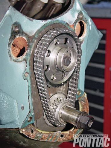
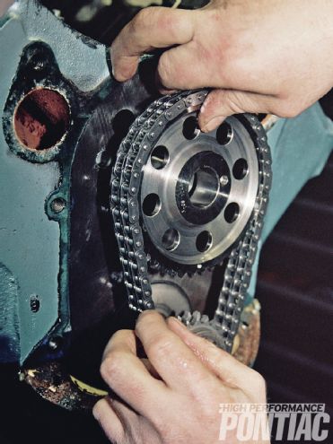 7 The timing chain and gear set looked as if the engine was never run, and had only two degrees of wear.
Let us now briefly explore these areas of concern:
Intended use: Nothing establishes the personality of an engine more than the camshaft. A high degree of overlap will create a rough idle with little or no vacuum. If you want power brakes and air conditioning, this must be recognized. Consider how you will use your Pontiac. You cannot have the best performance on the dragstrip and have the engine run like a stocker on the street.
Displacement: A general rule with all things being equal is that as the displacement of an engine is increased, it is able to endure more intake and exhaust duration.
Intended fuel: Very short duration and overlap camshafts will build more cylinder pressure at low engine speeds, producing more torque but increasing the sensitivity to octane at light load. A trick on some larger Pontiac engines is to run high compression and increase the overlap to kill some of the cylinder pressure at low speeds and part throttle. This will often allow the use of pump gas.
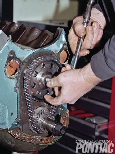 8 In preparation for the phasing process Craig turned the crankshaft two full turns opposite of rotation to seat everything and take out any slack.
Compression ratio: As the compression ratio of an engine is increased, it can also accept more overlap in the cam grind.
Cylinder heads: Knowing the lift point at which the intake and exhaust ports reach static flow is essential in picking the cam. Static flow is reached when the valve is lifted higher, but there is no increase in the flow rate and sometimes the flow even drops. Why would you want to lift the valve to 0.600 inch if the cylinder head stops flowing at 0.470 inch?
Intake manifold: For the engine to produce the best performance, the intake manifold needs to operate efficiently in the same rpm range as the camshaft. Installing a cam that works to 6,000 rpm and bolting on an intake manifold that is out of breath at 4,500 rpm will produce disappointing results.
Weight of the car and driveline selection: We all buy horsepower but drive torque. A heavy Pontiac needs torque at low rpm to get moving. If the cam that you choose shifts the power band to a higher rpm, then the car will need to have a very loose torque converter and a high numerical gear ratio to accelerate properly. As the vehicle weight is reduced, the power band of the engine can be shifted to a higher rpm.
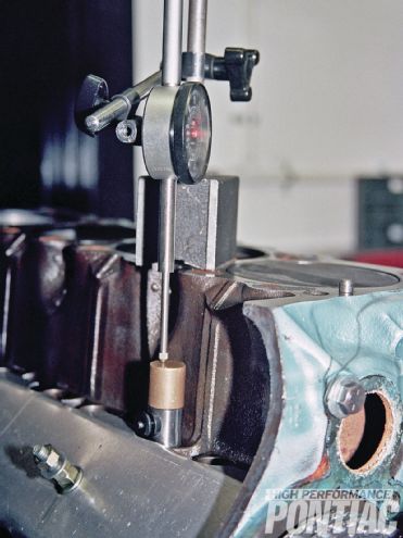 9 TDC was confirmed and lifter movement traced with a dial indicator.
Duration: As duration is increased, the rpm at which peak volumetric efficiency will occur is raised in lock step. Thus, a cam with 220 degrees of duration at 0.050-inch valve lift will produce peak power lower in the rpm range than one with 250 degrees duration at the same lift. Also keep in mind that the longer the valves stay open in crankshaft rotational degrees the greater the chance that a piston-to-valve-clearance problem may occur. The clearance between the piston and the valve needs to be checked with the cam profile that the engine will use.
Lift: As valve lift is increased, a concern for valvespring design becomes more apparent. A high-lift camshaft requires valvesprings that will not enter coil bind when the valve is fully open. These springs also have higher installed and open pressure that decreases both the life of the spring, camshaft, and valve lifter. Increased pressure tends to make the valvetrain noisier.
Lobe separation angle: LSA is an indication of overlap but is not all-inclusive of the amount of time both the intake and exhaust valves stay open. As LSA values go numerically lower, it is an indication of increased overlap. As overlap is increased, the engine becomes less efficient at low rpm and both idle instability and hydrocarbon emissions are increased. The amount of vacuum the engine produces at idle is directly linked to overlap, and thus, LSA.
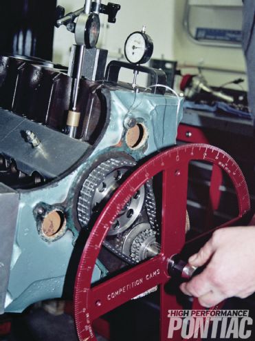 10 With the degree wheel in place, we found the camshaft was at 107.5 degrees instead of the desired 106-degree position.
Cam phase: Better known as degreeing in the cam, the phase of the cam should be checked with a degree wheel. Usually referenced from the intake lobe centerline. The position of the cam can be either straight up, advanced, or retarded. Straight up means that you checked the cam phase using a degree wheel and it is installed exactly at the intake centerline—not that the dots on the timing gears line up.
As the camshaft is advanced from the intake centerline, the power band is shifted lower in the rpm range. Conversely, when the cam timing is retarded, the rpm that peak power is produced is raised. Cam phasing can impact the piston-to-valve clearance. The clearance needs to be checked with the cam installed in the proper location. As the timing chain wears, the phase of the camshaft will retard. Craig confirmed the timing chain wear in The Mule when installing the new cam. It was 2 degrees.
Camshafts designed for a roller follower (either hydraulic or mechanical) open and close the valve quicker, since the wheel has the ability to follow a more aggressive ramp. In addition, there are some reductions in friction.
 11 The crankshaft gear has multiple positions so Craig moved it one notch and the cam checked in at 105.5 degrees, just 1⁄2 degree shy of the specification.
With the new cam installed in the required position, the Mule was buttoned up and mounted to the dyno cart. The mill ran great as always.
After experimenting with the tune-up, Craig found that it still liked the #79 jets in all four corners of the carburetor and wanted about the same ignition lead. The Edelbrock heads with the old cam made the most power with 34 degrees BTDC, and saw no gain when moved up to 36 degrees BTDC or down to 32 degrees BTDC. The results were close to those numbers with the new cam—the Pontiac liked about 36 degrees BTDC with margin of error differences when both 34 and 36 degrees were tried.
With the larger cam and increased valvespring pressure, the engine on average picked up 10 hp (448.11 to 458.1) and about the same amount of torque (550.23 to 561.1) when referenced from 3,300 rpm to 5,300 rpm. The peak horsepower went up 18.8, but the peak torque just 3.8 lb-ft. However the old cam produced peak torque at 3,500 rpm, while the new grind matched that torque figure at the same engine speed, and also extended the peak torque to 4,400 rpm.
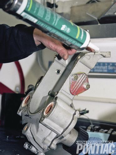 12 He then cleaned and treated the timing cover to fresh silicone sealer before installation with its gasket.
The real gain with the new cam was at 5,200 rpm, where power went from 486.4 to 521.6—a whopping 35 ponies! The horsepower still nosed over after 5,300 rpm, but since the level was higher the results are better. At approximately 5,400 rpm, the new cam still had nearly a 20hp advantage. But the engine was still rpm limited in relative terms. Reference the dyno charts for the comparison between the two cam grinds.
The upstairs power gains came at bottom-end losses though. At 3,100 rpm, the old cam had about 7 more horsepower than the more aggressive profile and more torque.
 13 The Edelbrock cylinder heads were then re-installed with gaskets and torqued to spec.
None of this surprised us since duration will impact the engine speed that peak cylinder fill and horsepower occurs. For this reason, the best-running Pontiacs are those that take a system approach to the engine build, incorporating all aspects of the vehicle and use—not simply chasing a dyno number.
Engine Displacement: 467 ci
Bore/Stroke: 4.185 / 4.250-in
Bore/Stroke ratio: .9.8:1
Rod/Stroke ratio: 1.6:1
Bottom End
Block: Stock '75 455
Deck height: 10.205-in
Crank: Butler/Eagle forged
Balancer: Summit Street/Strip, steel, elastomer, 6.610-in, SFI 18.1
Rods: Eagle forged H-beam, 6.800-in
Bearings: Clevite, plain shell, tri-metal
Pistons: Butler/Ross forged flat-top with valve reliefs
Piston-to-deck height: .010-in below
Piston pins: Ross, .990-in floating, 0.155-in wall
Method to retain pins in pistons: Spiro Locks
Rings: Total Seal, moly top, ductile second, three-piece oil, 1⁄16-, 1⁄16-, 3⁄16-in
Rod bolts and head bolts: ARP
Balancing specs: Internal
Oiling System
Windage tray: Canton in pan
Crank scraper: Canton in pan
Oil pan: Canton Racing Road Race Series 5 quart, wet-sump
Oil pump: Melling M54DS high-volume
Heads
Type: Edelbrock aluminum D-Port
Combustion chamber volume: 87ccs
Compression ratio: 9.98:1
Valves: SS 2.11/1.66-in
Retainers: Edelbrock
Keepers: Edelbrock
Valve Guides: Edelbrock
Rocker Studs: 7⁄16-in
Rocker Arms: Comp Cams aluminum full roller, 1.65:1
Pushrods: Comp Cams Hi-Tech 5⁄16x8.900-inch
Cam
Brand: Comp Cams Xtreme Energy hydraulic roller
Grind: XR276HR / XR288HR
Duration At 0.050: 224/230-deg / 236/242-deg
Lift: 0.552/0.561-in / 0.572/0.594-in
Centerline: 106-deg / 106-deg
Lobe Separation Angle: 110-deg / 110-deg
Installed Position: 106-deg / 105.5-deg
Lifters: Comp Cams roller / Comp Cams roller
Valvesprings: Edelbrock / Comp Cams
Timing Chain: Cloyes double-roller
Induction
Carb: Holley 750-cfm HP
Intake Manifold: Edelbrock Torker II
Ignition
Distributor: MSD Pro-Billet Ready-to-Run
Wires: MSD 8.5mm
Exhaust
Headers: Hooker
Primary Tube Diameter: 1.75-in
Primary Tube Length: 32-in
Collector Size: 3.00-in
Gaskets
Brand: Fel-Pro
Parts Sources
Engine Components: Summit Racing Equipment, www.summitracing.com
Reciprocating Assembly: Butler Performance, www.butlerperformance.com
Reference the dyno charts for the comparison between the two cam grinds
Comp Cams 224/230-degree cam, #79 jets, 34 degrees BTDC
Comp Cams 236/242-degree cam, #79 jets, 36 degrees BTDC