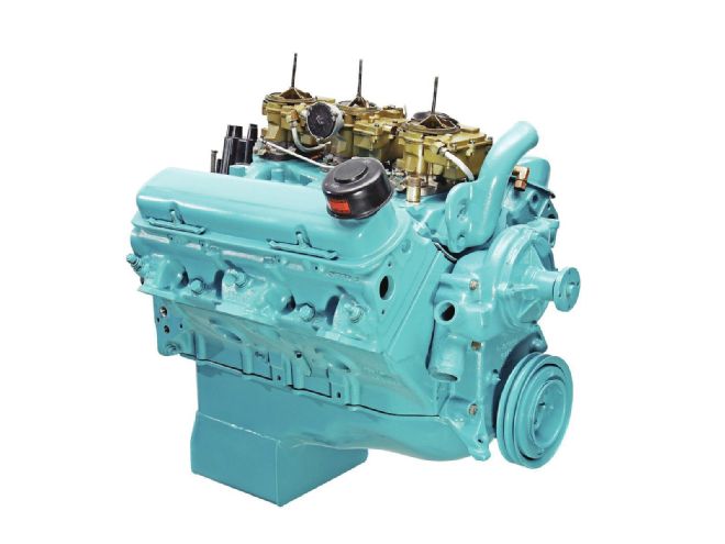
Over the last two issues, we've presented 34 engine assembly do's and don'ts related to the bottom end using an early 389 Tri-Power engine for illustration purposes. For the final installment, we return to DCI Motorsports in Atwater, Ohio, to photograph some top-end details and obtain more info from experienced engine builder Don Johnston.
As stated previously, this is not an Engine Building 101 article that will detail each step of the process. Instead, this guide will highlight some more advanced techniques a pro employs when pre-assembling and assembling a Pontiac engine. Consider these tips as companion information to the basic engine building procedures.
Like we did in Part 1 and 2, we will also discuss a few more common assembly mistakes that Don sees frequently in engines that come into his shop, so you can better avoid them.
Please keep in mind that many of these photos are mock-ups of how to perform procedures, therefore other parts that would normally comprise the final assembly of an engine but were not pertinent to the task illustrated may not be shown. Don also remembered a few additional great tips related to topics covered in previous installments after they went to press, so we added them in subsequent installments, like the timing-chain gear info in this story.
Since we can't cover every reader's individual situation with his or her engine build, we endeavored to discuss the more prevalent scenarios.
Our goal is for you to use these tips, along with basic engine building skills and procedures and good judgment, to assemble an engine for your Pontiac that will be reliable through many years of enjoyment.
1. Do
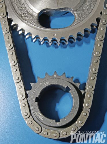
Line up the timing-chain gears correctly. The photo depicts the crank and cam gears lined up do-to-dot, which is correct. However, on timing sets that offer multiple keyways to advance or retard cam timing (like this one), Don has seen some assemblers line up the cam-gear dot with the “0” on the crank gear keyway instead. He also relates: “I usually don't use those positions on the crank gear, as I prefer to use offset keys on the cam because it allows me to degree in the cam, making adjustments as fine as a half degree.
2. Do
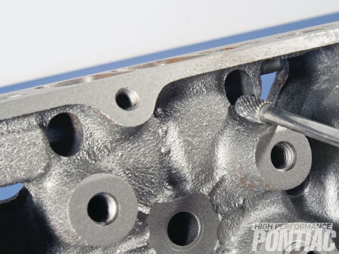
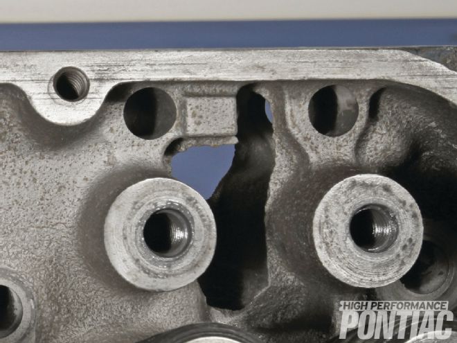
Tell your machinist if you're planning to use higher-ratio rockers, i.e., 1.65:1 from 1.50:1, as the pushrod holes in the heads will most likely need to be elongated with a die-grinder and a carbide burr to ensure there is no interference with the rods. The left photo shows stock round holes on one head; the right shows holes after grinding on another head and the burr is positioned under one of the holes for illustration purposes.
3. Do
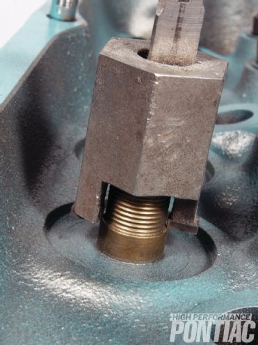
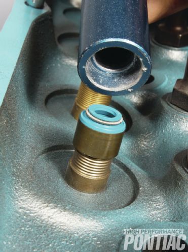
Tell your machinist if you're using positive valve seals—have him cut all the guides for them, as shown here. If instead you are using traditional O-ring-type seals and are ordering new valves, keep in mind that some valves no longer come with a groove for the O-ring. Here is the tool used to cut the guides (left) and the positive seal (prior to installation) with the tool used to install it (right).
4. Do
A non-Pontiac shop may change valve angles on Pontiac heads. Ask for stock angles for a stock rebuild. Custom angles can be done on a custom build, but they should be based on the engine builder's modifications and port work. If heads need to be milled, remember every 0.006 inch taken off the deck decreases combustion chamber size by 1 cc. For example, 0.060 inch milled would be 10 ccs. Anything over 0.030 inch milled from deck surface requires half as much material be removed from the intake port flange. Many will tell you to do an equal amount, but Don likes to leave some room for intake alignment.
5. Do
Measure from the topside of the installed valve seal to the underside of the retainer. You want the measurement to be equal to or more than the maximum lift of the camshaft (with the rocker ratio figured in) plus 0.060-inch.
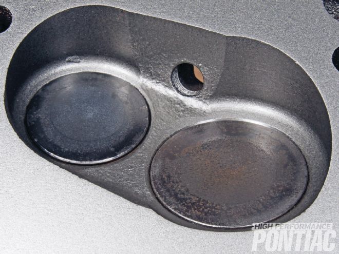
6. Do
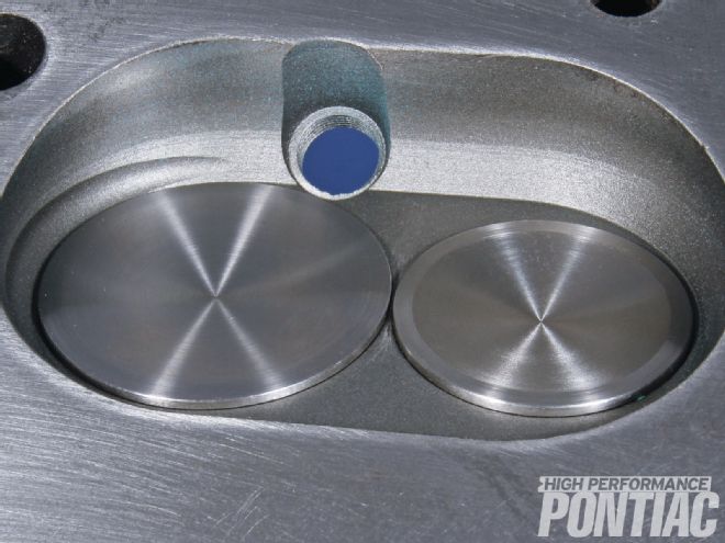
Check for sunken valves. The valves in the Pontiac chamber (top) are at the recommended height, which allows you to see the whole margin (edge) of the valve, but notice the intake valve in the BB Chevy chamber (bottom) and how it's sunken into the seat. If a valve is sunken too far, it will be shrouded and reduce low-lift flow. Don says, “The valve should be at least even with the surface of the chamber and not below it. I think the BB Chevy intake valve shown is sunken too far into the seat.”
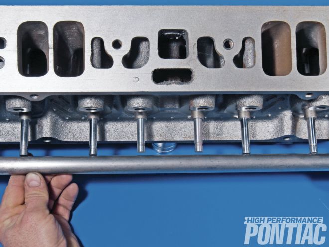
7. Do
Check the valve heights with a straight edge across the valve tips to ensure all are within plus/minus 0.020 inch of one another other. (If blueprinting, make sure all valve heights are equal.) You can also easily do this with the valvesprings installed if the machine shop assembled the heads for you. If they vary by more than plus/minus 0.020 inch, it indicates the seat heights are not the same. This may affect valvetrain geometry if it's excessive. (In instances where only some of the valves were replaced, the new ones may have been ordered in the wrong length.)
8. Do
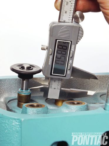
Check valvespring installed heights to ensure they are equal and at the manufacturer's or machinist's recommendation. The first measurement here reveals 1.732 inch, but 1.700 inch is what Don wants. Adding a 0.030-inch shim under the spring nets a 1.702-inch height, which is close enough as plus/minus 0.010 inch is the accepted tolerance.
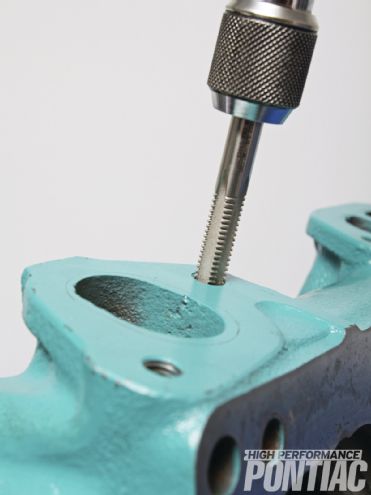
9. Do
Run a cleaning tap through all the threaded bolt holes in each head to ensure proper clamping force and torque readings. (Do it before you install the heads to avoid getting metal shavings in the engine.)
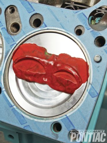
10. Do
Check piston-to-valve clearance. Apply modeling clay to the top of the piston where the valves would contact it. Add a light coat of oil to the top of the clay so it doesn't stick to the valves.
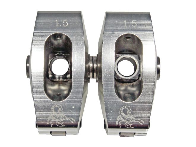
11. Don't
Install the rockers with the fulcrum facing the wrong direction—the flat machined surface shown on the right should be facing up, as it provides a flat surface for the locknut to tighten against.
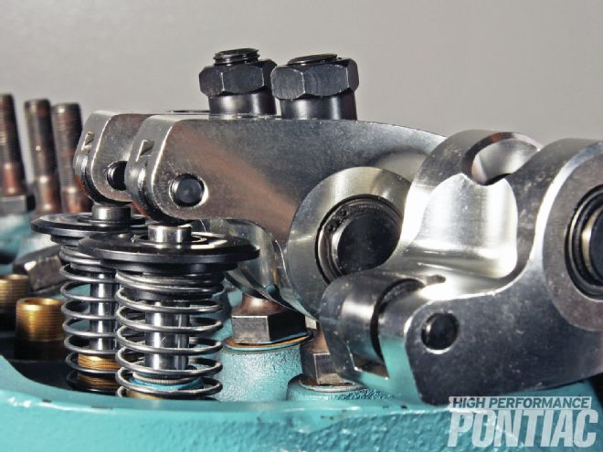
12. Do
Check for interference at the rocker and retainer as you turn the engine over. As you can see, there is no interference with these Scorpion rockers. You can also see the concave shape on the rocker (flipped over in the photo for illustration purposes) that provides clearance for the retainer. Don is using lightweight checker springs, but this procedure can be performed with the valvesprings that will be used on the engine.
13. Do
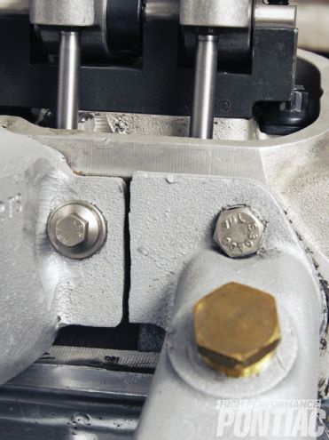
14. Do
Separate the intake coolant crossover from the rest of the intake on modified engines with an aftermarket manifold. It eases intake swaps and makes aligning the intake manifold with the head ports easier, since there is no worry regarding the coolant seal at the front of the manifold and timing cover.