In the last issue we presented 18 engine assembly Do's and Don'ts related to the bottom end using an early 389 Tri-Power engine for illustration purposes. For this installment, we returned to DCI Motorsports in Atwater, Ohio, to photograph more and learn the details from experienced engine builder Don Johnston.
Keep in mind this is not an Engine Building 101 article that will detail each step of the process. Rather it provides more advanced techniques a pro employs when pre-assembling and assembling a Pontiac engine. The tips in the story should be used in addition to the basic-engine-building procedures.
As we did in Part 1, we will also discuss a few more common assembly mistakes that Don sees frequently in engines that come into his shop, so you can better avoid them. Top-end info will be covered in the next issue.
Don’t
Use sealer behind the rope seal.
Do
Drill a 3⁄16-inch-deep hole in the center of the rear main seal groove with a 0.120-inch drill bit and install a 1⁄8x3⁄8-inch roll pin to keep the seal from rotating. It’s added insurance to work with the anti-rotation grooves already in the block. (Note the pin shown has not been installed yet and is just sitting where the hole should be drilled for illustration purposes.)
Do
Install the rope seal leaving material sticking up on each side so both can be cut perfectly flat. Work the seal into the groove with a socket or a dowel or something with a smooth, round surface. It must seat the seal properly so the anti-rotation grooves and roll pin keep it in place but not crush it too much because it still must seal the crank. This rope seal from Best Gasket (PN 6380 S) is impregnated with graphite, which the company says reduces drag and helps seal against the crank.
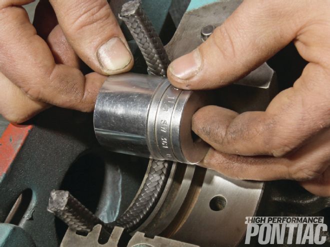
Do
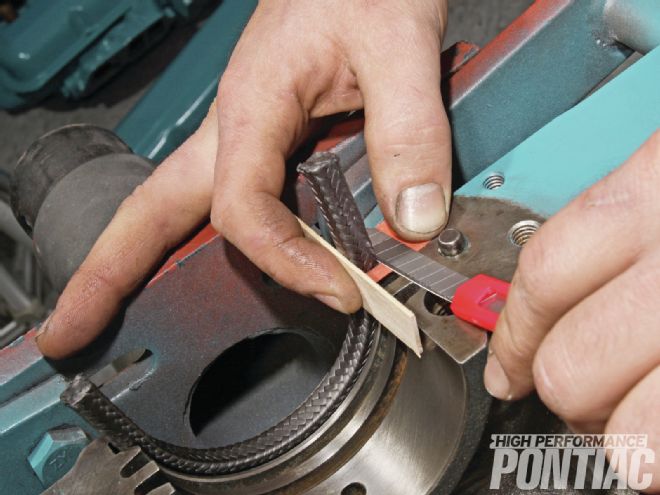
Trim the seal with the cutter and with the shim in place to ensure the end of the seal extends slightly above the block surface. This allows the finish crush to be done by the crank upon installation. The wood stick protects the finger from the blade. All these tools are provided in the Best Gasket kit. After cutting, roll any slightly frayed edges too short to trim back into the seal. Repeat steps 1 through 3 for the cap.
Do
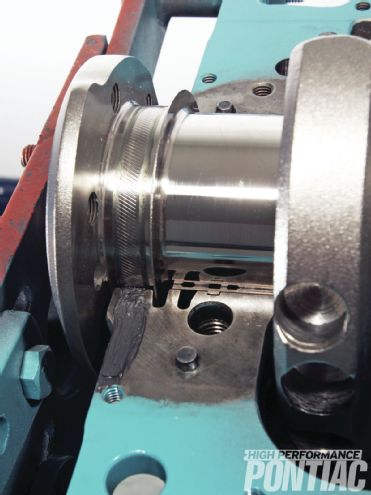
Use a little RTV on each seal end and between the cap and the block to avoid leaks.
The tips in the story should be used in addition to the basic-engine-building procedures.
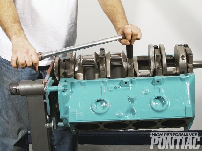
Do
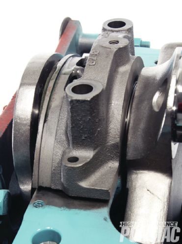
Torque all the main caps properly to draw the rear cap down so you don’t bend the crank. (See how it’s sitting up off the block in the photo?) First, install the main cap bolts and hand tighten. Next, tighten them in this order: #5 (rear), #3, #1, #4, and #2; then repeat until torqued to spec. The number 1 to 4 caps are torqued to 100 ft-lb, the rear cap is 120 ft-lb. Torque the bolts in increments—50 ft-lb, then 75 ft-lb, then 100 ft-lb, and finally the rear cap to 120 ft-lb when using factory fasteners. Studs require different torque settings.
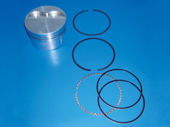
Do
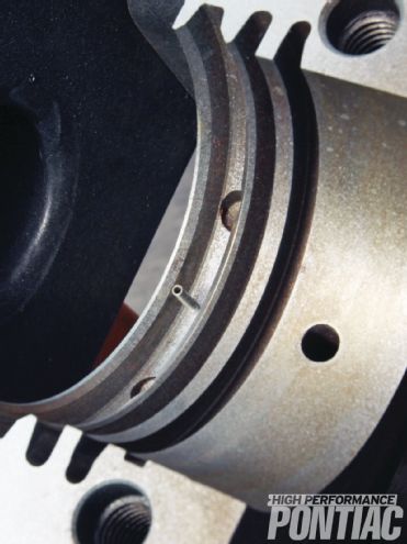
Make sure the ring gaps are opposite one another when installed on the pistons to get a better seal for initial startup, despite the fact that they will ultimately rotate on the pistons. Yes this is an easy one, but it’s forgotten many times, according to Don. Stagger the oil-ring wipers as well at 10 o’clock and 2 o’clock relative to the wristpin position at 12.
Do
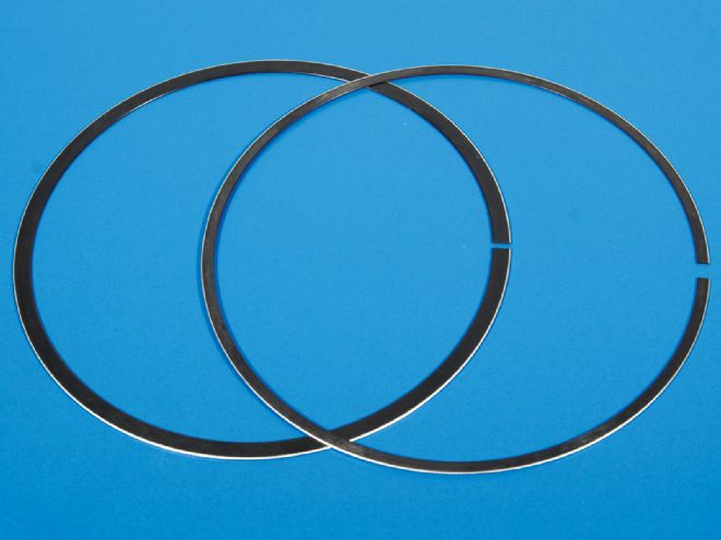
When using gapless rings, remember that the second ring is a two-piece (the top may be as well), so install it with the gaps opposite one another and with the thinner ring on the bottom.
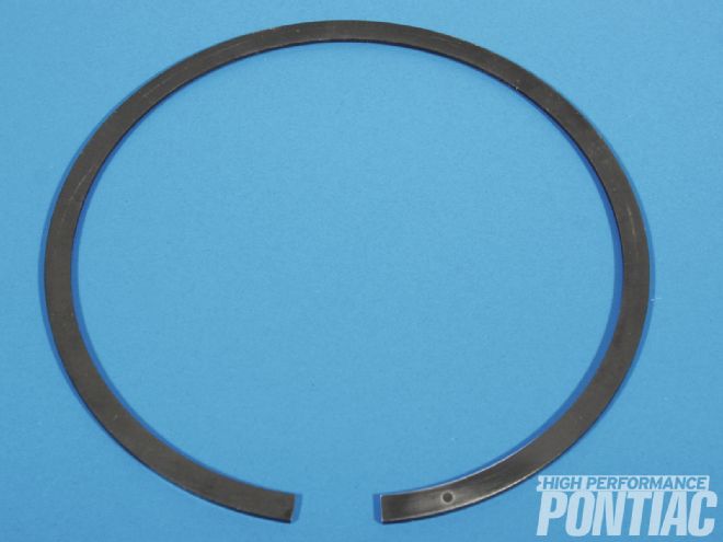
Don’t
Install the rings upside down. If there is a dot on the ring like this one, it should be facing up. No dot? Check with manufacturer.
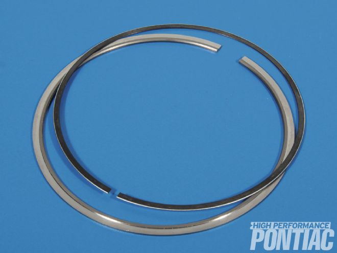
Don’t
Get the rings mixed up. When using gapless rings, the oil ring is similar in size and material to the second zero-gap ring assembly (the top may be as well). However, the oil ring is wider (left).
Do
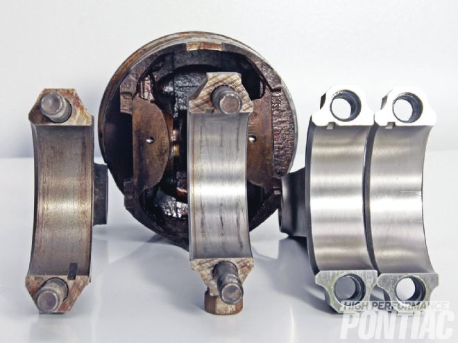
Make note of which rods you are using. When standing by the cylinder bank that received the piston and rod, on the factory Pontiac rod, the bearing tang faces toward you when installed. On the factory BB Chevy rod, Eagle Specialty Products (www.eaglerod.com) Chevy rods commonly used in Pontiac stroker builds (2.200-inch rod journal), and Eagle Pontiac rods, the bearing tangs will face away from you (below, from left to right: factory Pontiac rod, factory BB Chevy rod, Eagle Chevy rod, Eagle Pontiac rod).
Do
Use ARP Ultra-Torque Fastener Assembly Lube to ensure proper and consistent connecting-rod torque specs.
Do
Ensure that once installed, the cam moves freely with no tight spots as it rotates. If it doesn’t, it indicates a bearing is not installed straight, there may be an improper chamfer on the leading edge of a bearing, or the tunnel may not be line honed properly.
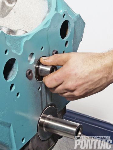
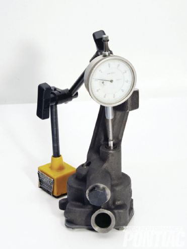
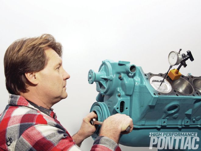
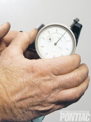
Do
Find true TDC. You need it to ensure the balancer mark matches TDC. This also needs to be done before degreeing the cam and checking piston-to-valve clearance. (Since degreeing the cam warrants a story unto itself, it will not be covered in this article.) Bring the piston to TDC and attach the dial indicator on the piston with a preload; then set it to zero. The dial indicator must be positioned dead center on the piston, otherwise the piston will rock on its pin and cause a false reading.
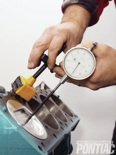
Do
Rotate the reciprocating assembly clockwise to take the piston down the bore. Then, while watching the indicator, rotate the reciprocating assembly counterclockwise (the needle will move as you do this) past TDC.

Do
The point at which the needle reverses direction on the indicator is true TDC. Go back past that point and come up on it again; stop on the exact point the needle reverses. In this instance, true TDC is at 3-degrees on the indicator.
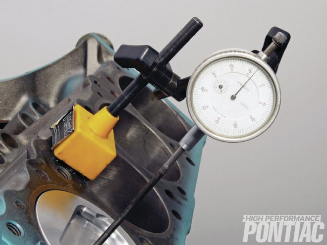
Do
To double-check it, Don resets the indicator to zero and repeats the process. If the dial indicator reads zero the instant the needle direction reverses, it is set to TDC.
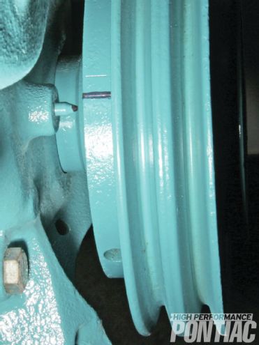
Do
Leaving the piston at TDC, check the relationship between the timing mark on the timing cover and that on the harmonic balancer. The mark should be at zero (TDC) on the balancer. As you can see on this ’59 setup (that has no numbers—ugh), it’s a few degrees off (for illustration purposes). On later balancers that use elastomer (up to ’66 doesn’t), it means the inertia ring has slipped on the balancer and should be replaced.
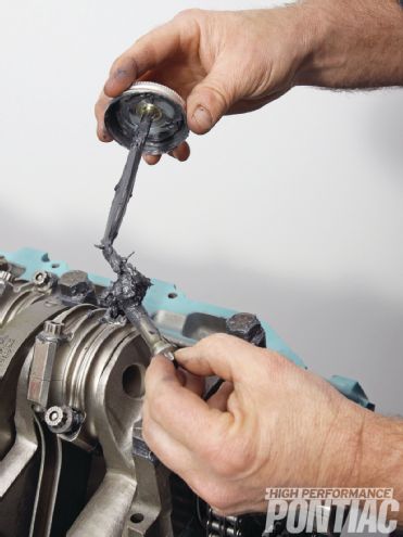
Do
Smooth the machined surfaces of the pump body and cover plate, as well as the flange that bolts to the block (sand with 220- and 320-grit on a flat surface) to prevent oil from escaping.
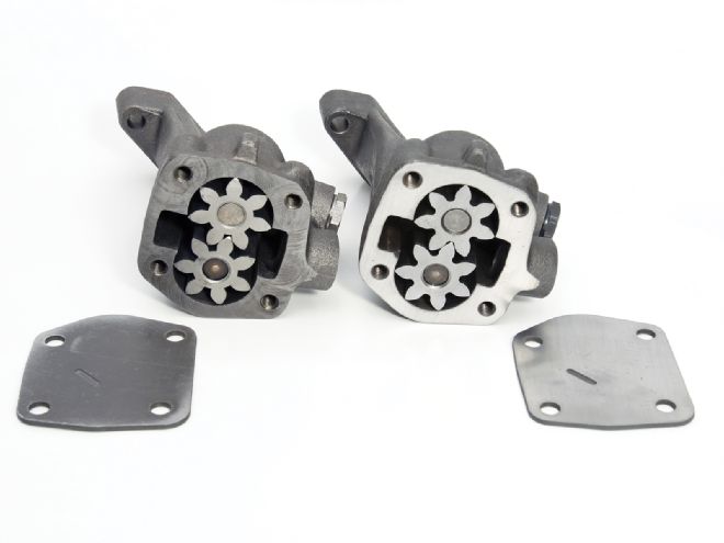
Do
Put the plate back on and torque the bolts to 15 ft-lb. Then set up a dial indicator to check the up-and-down movement of the gears and ensure there is still enough clearance between them and the cover plate (0.0015 to 0.0020). If you can’t pull up on the shaft at all, there is no clearance. That will cause the gears to dig into the plate and put metal through the engine. To correct it, sand the bottom of the gears on a flat surface with 220- and 320-grit.