
Well, I made it back out into the garage again this past weekend. Hopefully it’s a sign that work on the ’57 Chevy project has restarted in earnest. As you may recall, the last time I got out there I installed my new ignition system (a new PerTronix distributor, coil, and plug wires). This past weekend I focused on the fuel system.
When I first gained possession of the Chevy it was basically just a bare cab and chassis; all that was left of a well-picked-over parts vehicle. As I began putting together my rodstoration game plan, one of my ideas was to retain the cab-located OEM-style fuel tank. As I progressed I began having second thoughts. The more I thought about it, the more I recalled the cab fumes I used to live with in other old pickups I’d owned, and since I needed to buy a new tank anyway I might as well go for an LMC Truck rear-mounted unit, rather than a replacement behind the seat tank. As for the rest of the fuel system, I chose an electric fuel pump, fuel pressure regulator, and a 600-cfm Slayer four-barrel carburetor from Quick Fuel Technology.
So rather than babbling on endlessly, let’s take a look at the components I used and the ease in which they were installed. Geez, I just may finish this project after all.
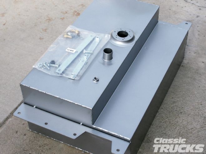
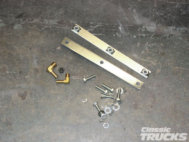
01 Rather than the replacement LMC Truck OEM-style in-cab tank, I chose their (part number 32-5912) 19-gallon steel rear-mount unit. Once unpacked from its shipping packaging I found the tank to be of the high quality I’ve come to expect from LMC Truck. The welds were good looking and uniform, and its silver powdercoating saved me the added work of prepping and painting it myself. The tank kit comes complete with mounting hardware, a fuel line fitting, and a plug for use with carbureted vehicles (the tank is equipped with two fuel bungs, one for fuel supply and one that can be used for fuel return lines when used in a fuel-injection situation.
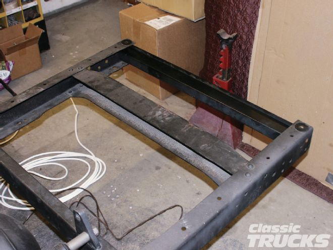
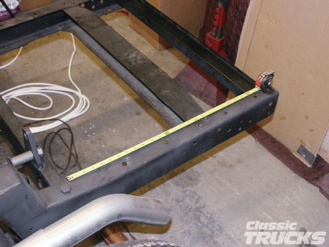
02 The #32-5912 tank is sized for use in the ’55-59 Chevy chassis, and it fit well, though it does require the removal of the frame’s rearward most crossmember. In this image you can see that I cut and inserted a piece of scrap steel channel tightly between the rails to hold ’em in place as I removed the factory crossmember.
03 Before proceeding, I double checked the frame measurements thinking I may just move the OEM crossmember rearward in the frame. But after thinking about it for a while I decided not to as the trailer hitch assembly I’ll be adding would end up serving as the rearmost crossmember anyway.
04 You’ll notice, if you look closely at the right framerail, that rather than drilling out the crossmember mounting rivets I cheated and just cut the crossmember out with a cut-off disc. I did it this way because, rather than mounting the tank on the lower surface of the framerails, I’ll be mounting mine on top. I did it this way because I’ll be raising the bed floor above the C-notches I had added to the frame and it’ll allow the tank to ride higher and not hang down and be seen below the bumper from the rear as many are.
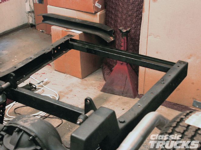
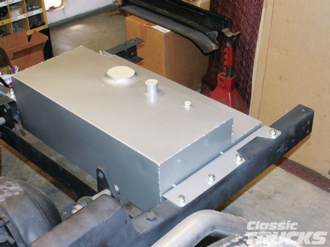
05 This image shows what I meant in the preceding caption. Again, having the option of mounting the tank on top of the rails worked perfectly in my situation.
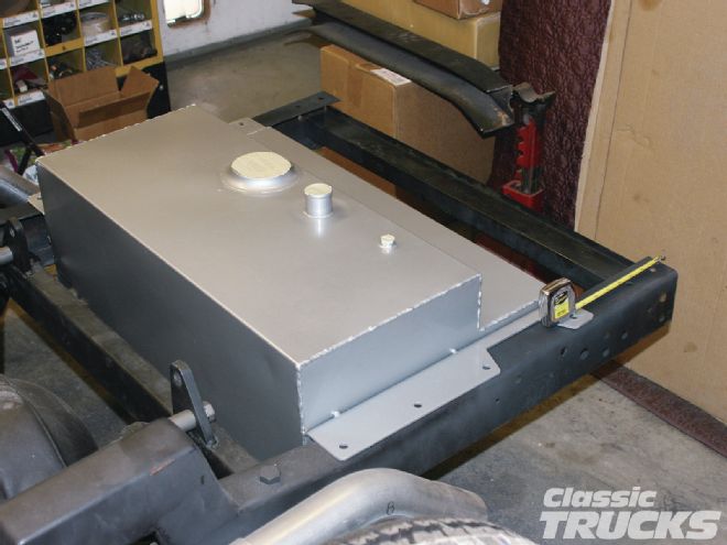
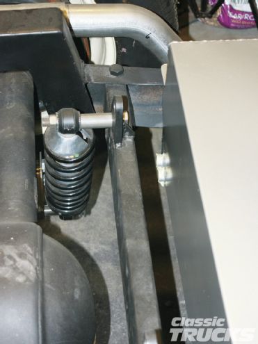
06 After locating the tank so there was enough room between it and the coilover shock crossmember I clamped the tank in place and drilled the mounting holes in the upper surface of the framerails. I also ended up having to remove the top domes of the crossmember mounting rivets so the tank flanges laid flat on the rails.
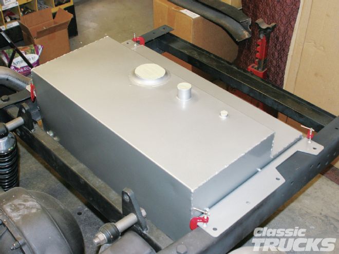
07, 08 Next, I used the hardware supplied with the tank and bolted it up.
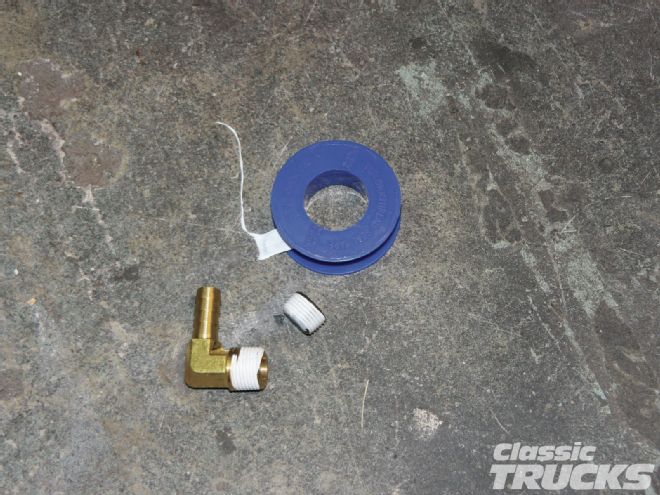
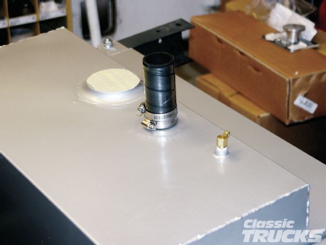
09 With the tank in place I then applied thread sealer to the fuel hose fitting and the fuel return plug and threaded ’em into the bungs on the tank.
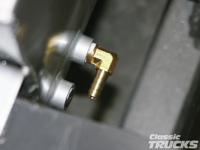
10, 11 These images show the fuel inlet/outlet bungs in the lower right-hand edge of the tank. I installed the fuel hose fitting in the innermost bung so there would be a sharp bend in the fuel hose connecting the tank to the hard line I’ll be using to route the fuel toward the engine.
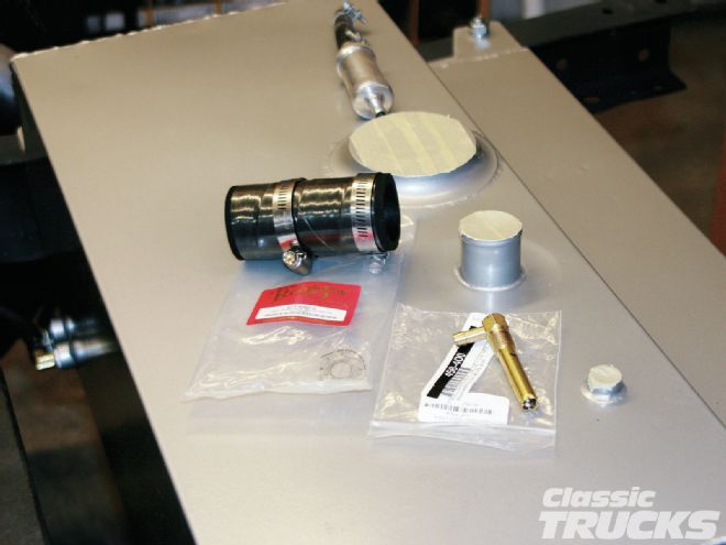
12, 13 As usual I had forgotten a few items when I placed my initial order with LMC Truck. Luckily I had the components I needed on hand (for another one of my projects). I borrowed a 11⁄2-inch I.D. x 4-inch fuel filler hose and a combination fuel tank vent and roll-over valve I had purchased from Speedway Motors a while ago.
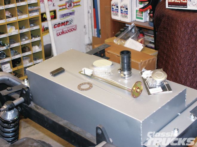
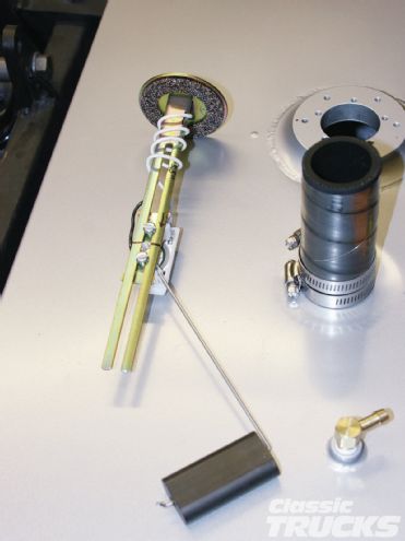
14 At least I’d had the forethought to order the fuel gauge sender (part number 32-4002) from LMC Truck along with the fuel tank. This particular sending unit is a 240/30-ohm sender for use in aftermarket fuel gauges. For the record, the correct LMC Truck sending unit for use with a stock Chevy gauge is #32-40011. You can also see the cool bed floor-mount aluminum pop-up fuel filler assembly I’d ordered as well. The filler assembly will work perfectly with the truck’s raised bed floor.
15 The fuel sending unit is a universal-type which means you’ll have to follow the instructions and trim the length of the main frame, locate the rheostat at the correct height, and trim the float rod to the recommended length as well.
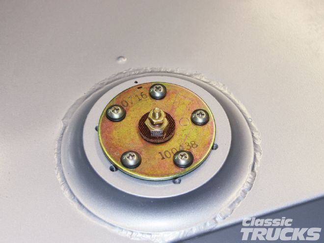
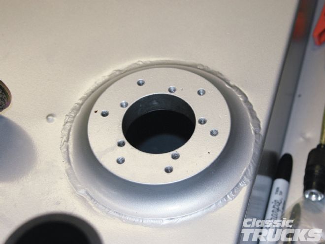
16, 17 The flange of the LMC Truck custom fuel tank is drilled for nearly any sending unit bolt pattern that one may run across. The holes are drilled and tapped, but do not go all the way through the flange so there’s no worry about any of the unused holes that are not covered by the sending unit mounting plate.
18 With the tank end of the system handled I began working on the fuel lines using a combination of 3⁄8-inch I.D. hard-line and rubber fuel hose. The first section utilized a 5-inch section of hose from the tank fitting to the first section of hard line that I had shaped to follow the C-notches on the framerails.
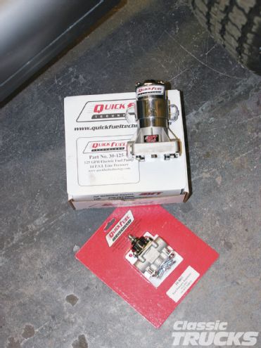
19 Just forward of the C-notch section I mounted my electric fuel pump. On the enthusiastic recommendation of a friend (who’s an accomplished engine builder) I chose to use a trio of Quick Fuel Technology components. Here you can see the fuel pump (part number 30-125-1) and fuel pressure regulator (part number 30-803).
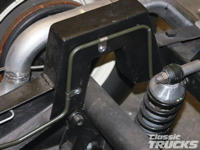
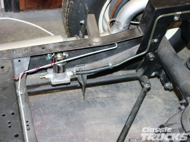
20 I mounted the QFT electric fuel pump to the inner section of the right-hand framerail. Though the fuel pump is a high-pressure unit, it’s made to push fuel rather than pull it, so it’s important that it be mounted a bit below the fuel tank outlet if possible. Mine is below that level, though I’m a bit concerned because of the C-notch. I may have to relocate the pump in the future, but I’m hoping I won’t have to.
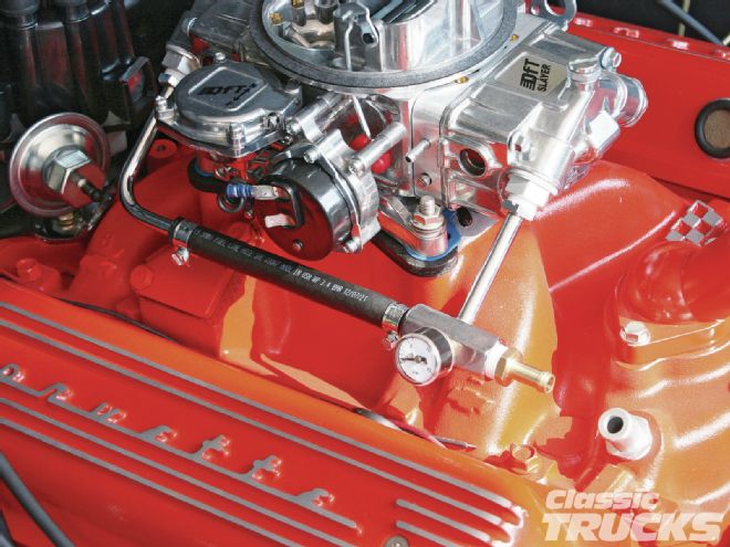
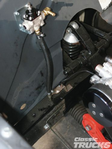
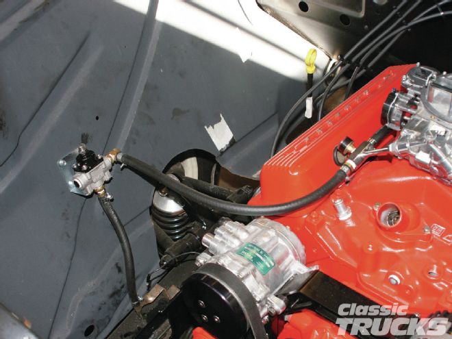
21 I ran the hard line forward from the pump to the engine compartment along the inside of the right framerail. I mounted the QFT regulator on the right side inner fender and connected it to the hard line via a length of fuel hose. The QFT pump puts out a steady 14 psi and the regulator is set at the factory specs with a 6 psi output.
22 As I said earlier, I chose the Quick Fuel Technology components on the recommendation of a very knowledgeable friend, but I still did my homework before ordering my components. I learned that the QFT Slayer Series carburetor is designed with many of the same engineering innovations and features that are built into all of the company’s race-winning carburetors. That led to the development of new (and affordable) 600- and 750-cfm vacuum secondary street carburetors. Their design utilizes a secondary metering plate with changeable jets that eliminate the secondary metering block unneeded for most street applications. The Slayer Series carbs also offer all-aluminum construction and hand-built quality.
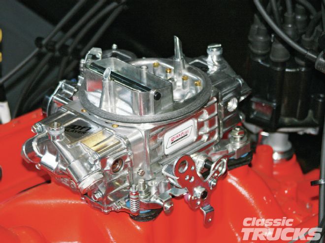
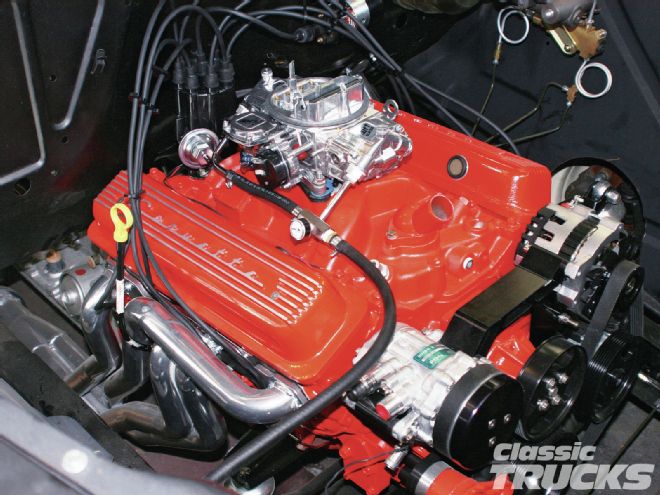
23, 24 Once I mounted the carb, I then began plumbing it into the fuel supply system. First I made the carb inlet assembly using a couple of carb fittings I had hanging around the garage and a section of fuel hose of the correct length. From there I ran another section of hose from the carb to the QFT fuel-pressure regulator mounted on the inner fender. And that was that – one step closer to a drivable classic pickup. I’ll hopefully make it back out into the garage before the next deadline, so keep your eyes peeled for the next step in my seemingly never-ending saga.