The reason for Project Pure Poncho’s existence (aka the Mule) is for research and development. We want to explore as many aspects of engine theory and performance that we can, while still being relevant to the readership. Thus, when Victor Weitzel at Gear Head Designs contacted us about trying his company’s new Gear Heads Pontiac-dedicated supercharger kit, we were all ears. At our testing and engine-building facility, RaceKrafters Automotive Machine, owners Bob and Craig Wise were just as excited about putting a big fan on the front of a Poncho. All we needed to do was make it happen.
Following a format that we have used before with Project Pure Poncho, this primer will explore the theory of forced induction and describe the supercharger package, while another article elsewhere in this issue will be focused on the empirical, the prep for the dyno test, the test, and the results.
It’s all about volumetric efficiency
An engine can breathe one of two ways: naturally or artificially. When the cylinders are being filled solely by the pressure differential between the bore and the atmosphere, it is naturally aspirated. Once another means is employed, it is identified as artificial or forced aspiration or induction. This can be accomplished by either a supercharger or turbocharger.
Nitrous is a unique approach to cylinder filling and by definition is not technically forced induction. It is a chemical method of putting more oxygen into the cylinder rather than through mechanical means. For that reason, many identify nitrous oxide as a power adder and not forced induction. This primer will not include any discussion on nitrous oxide.
When an engine fills its cylinders via the natural depression or pressure differential, it needs to be understood that the bore is not completely filled. The measure of how full the cylinder becomes is called volumetric efficiency (VE). It is something that cannot be determined on the enthusiast level. To accurately assign a number, the amount of airflow into the engine needs to be identified along with the discharge from overlap and the storage capability of the intake manifold.
On an engine dyno that employs an airflow meter, VE is loosely determined by the volume of air entering the induction track in relation to the swept volume of the cylinder bores. That method does not take into account the storage of the intake manifold or that lost during overlap. It is an indicator that has no real value when tuning an engine on our level. When Detroit engineers calculate VE, they have all of the other data and can accurately define the cylinder fill.
The important aspect of VE, which HPP readers need to understand, is that in a normally aspirated engine the cylinder is not 100 percent filled, and at peak torque, the VE is the highest.
A traditional Pontiac engine will see around 80-85 percent true VE at peak torque and approximately 5-6 percent lower readings at peak horsepower. This is due to the pumping and flow limitation of the induction track and the exhaust path. When an engine produces more power, the VE is increased. The only way power can be gained without impacting the VE is with the ignition curve and air/fuel ratio. Those tuning areas are what allows for the most energy transfer from the charge that already exists in the bore. Simply put, if you want to make more power, you need to fill the cylinder with more air and the proper amount of fuel. The fuel and air mix that enters the bore is called the charge.
Traditional modifications, such as camshaft changes and increased cylinder head flow improve the VE and thus, make the Pontiac more powerful. The perpetual problem is that VE is always going to be limited. The flow loss though decreased through modifications will still be present, along with the natural effect of the variation in atmospheric conditions and barometric pressure. When the barometer is high and the air is dry, your Pontiac will make the most power. The cylinder will be filled more than on a day with adverse conditions.
The only way to further increase cylinder fill is through mechanical means—supercharging and turbocharging. Both types of artificial aspiration work the same in regard to their impact on VE. The difference is how the compressor wheel that pushes the charge into the cylinders is driven. A supercharger has only a compressor wheel that is driven via the crankshaft by a drive belt, while a turbocharger is propelled via the exhaust gases passing by a turbine wheel, and its attached compressor wheel fills the cylinders. The housing that holds either a compressor or turbine is called a volute. It has a snail-like appearance, and includes an inlet and a discharge.
When discussing superchargers there are two designs. A centrifugal style is what has a volute and looks like a turbocharger without the turbine housing. The other type of supercharger uses a scroll and is often identified as Roots or scroll-style. It sits on top of the engine and, in many applications, takes the place of a traditional intake manifold.
Both designs have good and bad aspects. It is accepted that a centrifugal supercharger is easier to retrofit to a normally aspirated engine, since it mounts on the front as an accessory, such as an A/C compressor would. A Roots-style blower packages easier but adds complications with hood clearance (especially with a carburetor), fuel lines, linkages, and so on. It is generally recognized that a scroll supercharger provides boost quicker and with cooler charge air, but can bring additional complications based upon the use and application.
Today the aftermarket offers both scroll and centrifugal superchargers. The Gear Heads Pontiac-dedicated kit uses a Paxton Novi centrifugal blower.
Other Considerations
Forced induction has the ability to raise the VE of an engine to 100 percent and way beyond. It is a function of the airflow in cubic feet per minute (cfm) of the compressor and the boost pressure created. Boost is the positive pressure above atmospheric that is generated in the intake manifold.
This is often confusing, since most supercharger companies rate the boost pressure at the discharge of the volute and not the intake manifold. If the airflow path is long or the manifold has a large capacity, the boost pressure that reaches the cylinders will be lower.
The cfm is a function of the compressor/volute design and the speed at which the compressor wheel turns. When viewed simply, one would conclude that the faster the compressor wheel is turned, the higher the cfm and greater the boost pressure. That would be correct, but only to a limit.
Every compressor is rated for adiabatic efficiency. In simple terms, it’s the ability to compress the air molecules without an increase in heat. It can be likened to determining how many people can fit into a room without uncomfortably raising the ambient temperature.
Though the industry identifies the heating of the air or the lack of it as the compressor’s adiabatic efficiency, it is actually a measure of adiabatic compression. The theory is to be able to compress the air as much as possible without excess heating. It is generally accepted that compression will heat the charge but only a minimal amount.
Heating of the air is important when it comes to performance. Engine power will be impacted by one percent for every 10 degrees F change in temperature. As the temperature rises, power goes down and as it cools the output increases. Thus, it is important to keep the compressed air as cool as possible or the VE will not improve as much as the cfm and boost pressure would suggest.
The adiabatic range of the compressor is a combination of the design of the wheel, volute, and operating speed. A compressor will be efficient to a defined speed and pressure, and then will dramatically ramp off in efficiency. When that occurs, the boost pressure may rise when read on a gauge due to the expansion of the charge from heating, but the effective VE will be diminished. There will be more on this in the dyno test article.
The need to cool the charge has brought about the integration of a heat exchanger in many forced-induction applications. There are both intercoolers and charge air coolers, the difference being that an intercooler has only air coursing through it. If charge (the air/fuel ratio) is passed through, then it is considered a charge air cooler.
An additional aspect of heating the charge is the propensity of evoking abnormal combustion, or what the enthusiast refers to as detonation or ping. Octane is the fuel’s ability to resist auto ignition through heat and pressure, and forced induction raises both. A supercharger usually produces cooler compressed air temperature, since it does not have one side of the unit exposed to hot exhaust gas as a turbocharger does.
Most of the power gain from forced induction is realized from the improved VE; the denser charge (the fuel and air molecules are closer together) put there is a side benefit—that is the pressure rise in the bore. In a normally aspirated engine when the piston is at bottom dead center, there is atmospheric pressure in the cylinder. Then as the piston sweeps toward top dead center, the area is made smaller and the pressure in the bore rises. This is a result of the compression ratio of the engine (the mathematical change in volume), the atmospheric pressure, and the volume taken by the charge.
When forced induction is applied, the beginning pressure in the cylinder is greater than atmospheric, and is a function of the boost level. Let’s apply some numbers to make this clear. We’ll assume that the atmospheric pressure is 15 psi and the boost pressure is 5 psi. Then the cylinder will be pressurized to 15 plus 5 or 20 psi before the piston starts to move upward. This higher pressure will then translate to a greater cylinder pressure when the flame expands across the bore and pushes against the piston.
There is no denying that the pressure rise from the forced induction is minimal compared to the gains from overfilling of the cylinder (VE) and the denser charge, but it does make a difference. For this reason, along with the improved VE, a forced-induction engine (especially one with a turbo) feels more powerful even when the boost gauge is reading zero. This is often not the case with a supercharger since it takes power to turn the compressor, and that is coming from the crankshaft.
The Gear Heads kit
The kit we received for testing was designed to work on a traditional Pontiac engine. It features a Paxton Novi supercharger and all of the brackets required to mount it in place. It also included the necessary pulleys to drive the unit and tighten the belt. In the basic form, it includes no ignition control, fuel delivery changes, or intercooling. It is a bolt-on supercharger in the truest form, and has a pulley ratio to build about 5 psi of boost on a large displacement engine.
Our installation was very straightforward and posed minimal issues. Keep in mind, we were working on an engine on a dyno that was not encumbered with an alternator, power steering pump, radiator, or fenders to get in the way. From HPP’s experience, the brackets and supercharger were very well designed. Though the install would definitely be more difficult in a car, the kit is very well thought out.
The only question that remains is: Will the Mule make power and not break with the improved VE? The answer is only a few pages away.
Gear Head Designs’ Paxton NOVI Supercharger Kits
According to Gear Head Designs, its Gear Heads supercharger kits will fit all Pontiac V-8s from ’58 through ’79 (except 265 and 301), as long as a ’69-and-later-style timing cover is used. It will fit ’64-’77 A-bodies, ’67-’81 F-bodies, ’62-’77 Grand Prix, ’58-’79 Big-Cars, and possibly more models. Some cars may need mild underhood brace clearancing.
Power steering is no problem according to the company, nor is aftermarket A/C, but factory A/C cannot be used. Stock pulleys, March 1- or 2-groove pulleys, or a March serpentine system (with or without aftermarket A/C) can be used. The large C-shaped alternator bracket used on ’70s Pontiacs may need light modification.
In the Kit
Gear Head Designs provides ready-made kits for its customers featuring a choice of superchargers, ranging from the Paxton Novi-1200 capable of 5-22 psi boost and up to 775 hp, to the Novi-1500 adjustable from 5-26 psi and up to 825 hp, to the race-only Novi-2200 that can provide 5-27 psi of boost and up to 1,000 hp. Each kit has a 1-year warranty and comes with a host of other required components, including mounting brackets; polished inlet tubing, filter, and couplers with clamps; polished outlet tubing, couplers with clamps; polished blow-through carb hat; adjustable blow-off valve; hardware for mounting; oil feed lines (unless the self-lubricated Novi-1200SL blower is used); timing cover gasket set (for engine oil feed systems); fuel regulator with boost reference and return; belt for supercharger; pulleys (blower pulley, blower crank adapter); idler, tensioner, and alternator tensioning clevis; and an installation manual.
Gear Heads Kit Pricing
NOVI-1200 $3,895
NOVI-1500 $4,295
NOVI-2200 $4,795
Not Included: The kit does not come with the required blow-through carb; electric fuel pump, lines, filter; or ignition upgrades. Gear Head Designs does recommend an MSD Pro-Billet distributor and 6AL boost timing master.—Thomas A. DeMauro
Paxton Supercharger Specs Blower Max RPM Max PSI Max CFM Max HP Inlet size Outlet size NOVI-1200 52,000 22 1,150 775 3.5-in 2.75-in NOVI-1500 55,000 26 1,200 825 3.75-in 2.75-in NOVI-2200 60,000 27 1,450 1,000 4-in 2.75-in Notes: The crossover to Vortech blowers are NOVI-1200=Vortech V1 - 2 SI series, NOVI-1500=Vortech V1 T trim, and NOVI-2200=Vortech V7 JT trim.
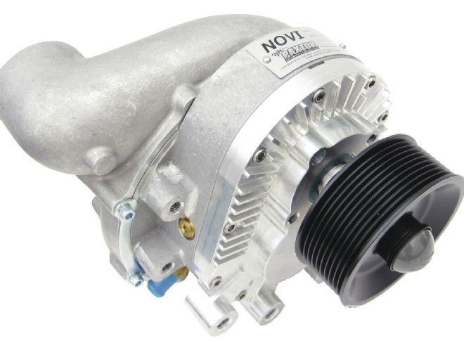
1. The centrifugal supercharger has its impeller driven by a belt from the crankshaft pulley and is mounted on the front of the engine.

2. A Roots-type supercharger is also crank driven, but uses rotors to generate boost. It mounts in the place of the stock intake manifold.
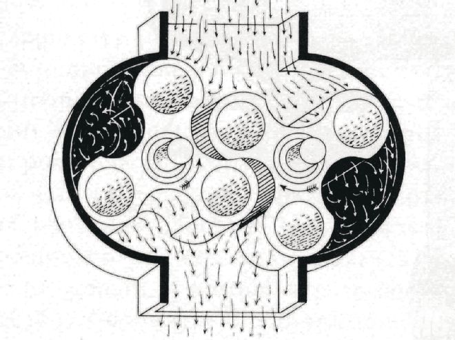
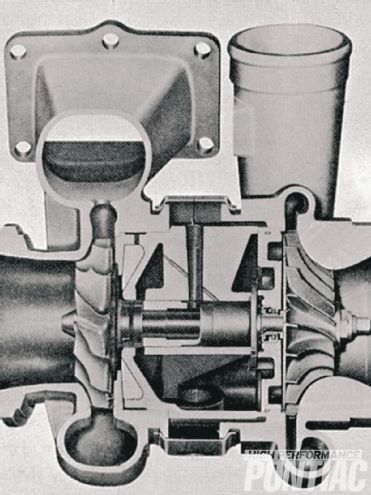
3. A turbocharger employs two impellers that operate in separate chambers but are connected to one-another. One, spun by exhaust pressure, turns the other on intake side to force air into the engine at higher than atmospheric pressure.
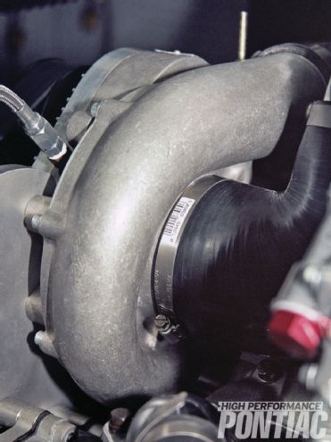
4. The volute for the supercharger can be seen here. This Novi-1500 unit required high-pressure engine oil to be piped to the bearing; the Novi-1200SL does not. Craig pulled oil from a port on the side of the block.
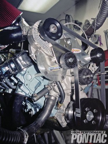
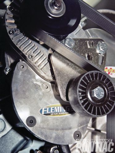
5. This billet bracket offered solid support, while packaging easily. The idler pulley to maintain belt tension can also be seen.
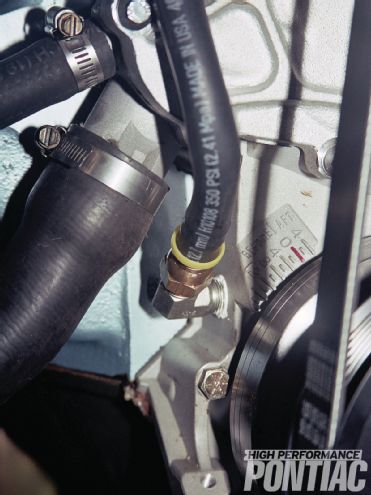
6. The return oil from the super-charger is drained into the timing cover, and the installation looks factory
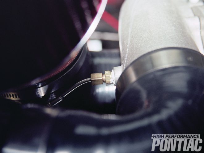
7. We installed two temperature probes to monitor charge heating. The first is in the volute discharge.
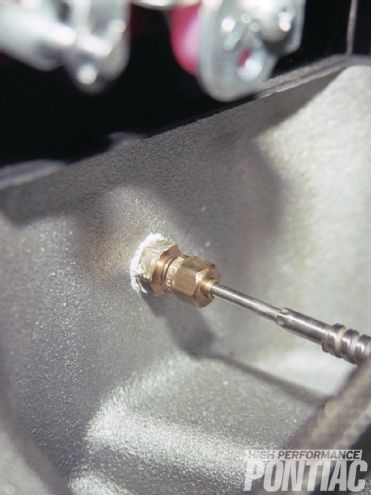
8. We also placed a temperature probe in the plenum of the intake manifold. With the two readings, we would be able to see the discharge temperature from the blower and the influence of a chemical intercooler we would be using on it.
9. The supercharger sits on the passenger side of the engine and offered little interference for the dyno-mounted electric water pump drive or anything else.
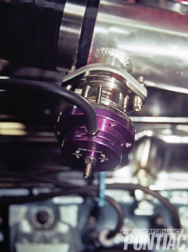
10. The Gear Heads kit included a blow-off (sneeze valve) to release pressure when the throttle is snapped closed quickly. It has the ability to act as a differential, and monitor pressure and engine vacuum for more defined control, and is a real benefit on a street application.
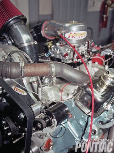
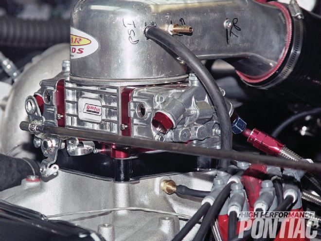
11. Since this is a blow-through design, a hat attaches to the air horn of the carburetor where the air filter assembly would normally be. Craig modified the carburetor hat so we could monitor boost pressure, as well as mount the chemical intercooler nozzle for a methanol intercooler that will be covered in the dyno test story. The blow-through carburetor was supplied by Quick Fuel Technology and its attributes will also be discussed in the dyno test story.
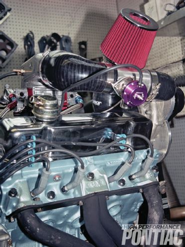
12. As you can see, the air filter, piping, and blow-off valve all package nicely, but hood clearance should always be taken into consideration when installing a supercharger. Gear Heads wanted the air filter to reside between the inlet pipe and the valve cover, but with the higher Mr. Gasket valve covers for rocker arm clearance, it would not fit there, so Craig changed its location.
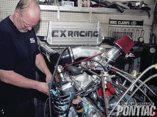
13. With the kit installed, Craig pulled the plugs to look everything over and discuss any tuning changes that may be required before the first run. See “Project Pure Poncho,” page 56, to learn how the engine was set up for the dyno test and its results.