 What better way to wile away an afternoon than by running some cams through a stout 440? This time, we wanted to see which worked better-a solid or hydraulic stick-when we tried to keep the "bigness" the same.
Without a doubt, solid cams carry a certain mystique. In the musclecar days, solids were factory-fitted in some of the hottest iron out of Motown, including the early street Hemi. There was a little extra status when laying out the engine specs and telling the boys, " . . . it's got a solid cam." Actually, all cams are solid. The real difference is in the lifters, with a corresponding change in cam-lobe profile to accommodate the requirements of the lifter. Solid cams have a reputation for higher rpm power, and for some, the image of a race-only piece. Solids require periodic adjustment, make noise, and are just a little different from what the average guy is running. For some, that's reason enough to want to run one.
We, however, were more interested in seeing what differences could really be found in power output. First, we offer a rundown of the differences between solid and hydraulic lifters, and why there may be power to be gleaned.
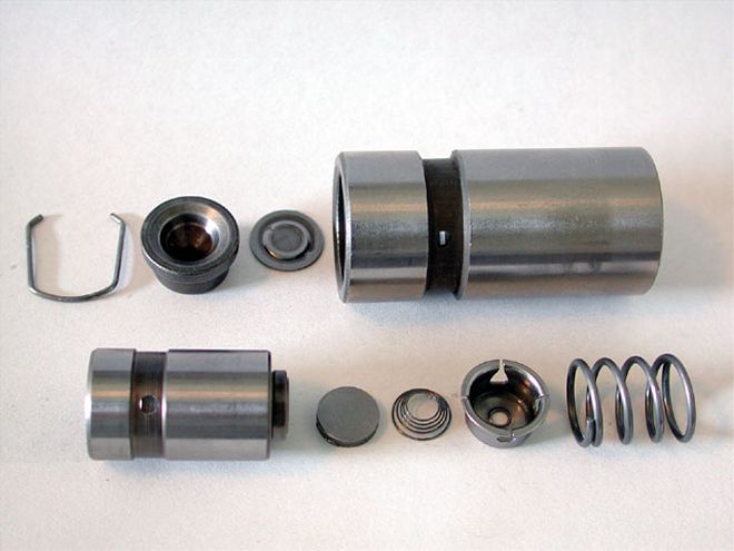 A hydraulic lifter includes this internal mechanism, which takes the slack out of the valvetrain, so the system always automatically runs at zero lash.
Hydraulics
Since the '50s, with a few notable exceptions, hydraulic lifters have been a Detroit norm. Hydraulic lifters self-compensate for valvetrain clearances, giving the consumer years of maintenance-free service. While hydraulic lifters themselves are much more complex than standard solid tappets, the accompanying valvetrain could be built much more simply and at a lesser cost, doing away with the provisions for valvetrain adjustment. Simple dirt-cheap, one-piece, stamped-steel rockers were the inevitable result. Best of all, the travel in the hydraulic mechanism soaked up variations in production tolerances with ease, undoubtedly streamlining the production process, eliminating the need to set valve lash at the engine plant and down the road in service. Hydraulics self-adjust to zero lash. They provide unrivaled quietness, a primary goal in OE engine design.
Hydraulics Or Solids For Performance?
All-out racing performance was never on the agenda when hydraulic lifters were conceived. However, the vast majority of performance cams sold are unquestionably hydraulic grinds. Some of the same attributes that made them a favorite with Detroit hold favor with many enthusiasts. Since most engines were initially set up with hydraulic cams, hydraulic performance cams are usually the most cost-effective replacement choice. Making a switch to a solid grind can come with quickly escalating costs, most often requiring the upgrade to adjustable rockers and compatible pushrods. Along with the cost, quieter operation and never having to adjust the valves make the hydraulic a tempting choice for dual-purpose applications.
Hydraulics work extremely well in moderate rpm applications-the range of most mildly modified street engines. Move up the performance, though, and the very hydraulic mechanism that makes them oh-so-sweet in a milder application can create problems. Why? Under the stresses of high rpm, the hydraulic piston, which serves to zero-out the clearances in normal operation, can either pump up or bleed down. These are two very different phenomena, both of which can hinder hydraulic-lifter performance.
All hydraulic lifters can absorb a small portion of the cam's lift profile in running, through fluid bleeding past the lifter's plunger piston during the lift cycle. In stock or mild street applications, absorption is likely negligible. Highly aggressive cam profiles and spring loads in a radical street or racing application can strain the hydraulic lifter's mechanism to the point where some performance potential is lost through absorption. Lifters with tight internal clearances and valving most accurately follow the cam's profile, and are termed stiff.
 We stabbed in a solid cam that we had custom ground to match as close to the hydraulic as possible. The specs were nowhere near the same, but the valve events were close to equivalent.
The second form of false motion is the better known problem of lifter "pump-up." The hydraulic lifter's plunger is continually under hydraulic pressure from the engine's oiling system. Under demanding circumstances such as high rpm, the valvetrain can partially unload. This unloading can occur during the onset of valve float, during spring surge, or with valve bounce on closing. Unloading can also occur when the effective spring load on the valvetrain is drastically diminished while the cam's lobe rotates over the nose at high rpm. The hydraulic lifter's plunger will quickly pump up any time the force of the oil acting on the hydraulic piston exceeds the force of the valvetrain on the lifter's plunger. This will cause the lifter to be temporarily overextended into a condition referred to as lifter "pump-up." The overextended lifter causes the valve to be held slightly off the seat when the camshaft is on its base circle, effectively hanging up the valves.
The aftermarket has developed some variations on the standard-issue hydraulic lifters. One of the first refinements was the introduction of anti-pump-up lifters. The concept is as simple as it is effective. In an anti-pump-up lifter, the light-duty retaining clip at the end of the hydraulic lifter's internal plunger travel is replaced with a heavier, more positive stop.
When used in conjunction with an adjustable valvetrain, an anti-pump-up lifter can be set so the internal plunger is at or near the top of its range of travel when the camshaft is on its base circle. When running, the anti-pump-up lifter is essentially adjusted so the piston is already pumped all the way up against the stop, eliminating the possibility of the plunger overextending. An adjustable valvetrain is, of course, required to utilize an anti-pump-up lifter as intended. Anti-pump-up lifters may also include changes to the lifter's valving or clearances to alter the bleed-down characteristics, although current theory holds that "stiffer" is better.
At what point can instability with a hydraulic lifter begin to hinder performance? The answer, unfortunately, is combination specific. Valvetrain weight and geometry, pushrod deflection, preload adjustment, spring load, and the cam profile's smoothness and intensity are some of the factors, along with rpm, that can upset a hydraulic lifter's ability to maintain valve control. Even oil viscosity and temperature have been reported to make a difference.
Though there are too many variables to pinpoint the rpm capability of a hydraulic-lifter camshaft, extensive experience in the use of hydraulic cams can suggest basic guidelines. Depending upon the camshaft/valvetrain/spring combination, standard hydraulic lifters can operate effectively in the 5,500-6,000-rpm range. Typically, anti-pump-up lifters can raise the rpm potential by 500-1,000 rpm more. Certainly, some have far exceeded these numbers, while other combinations experience problems at even more conservative levels.
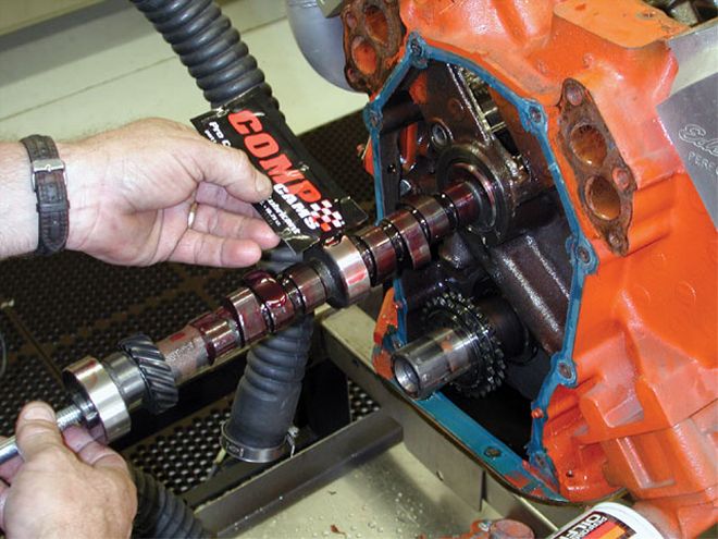
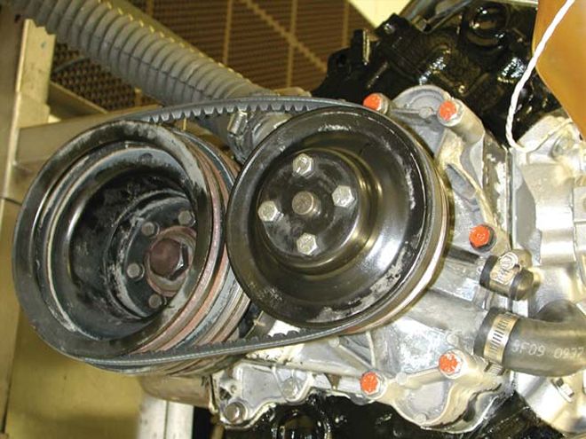
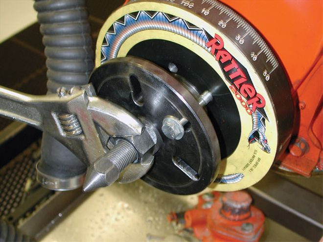 The most time-consuming part of changing the cam in a 440 was getting the damper off. The dry intake, shaft rockers, and flanged timing cover made a cam swap a breeze.
Solid Solution
Solid lifters are as the name implies-solid. There is no internal mechanism to take up clearance, and in fact, they require clearance to operate properly. This clearance is called the valve lash. Why, you may ask, is lash required? As the cam comes around to the base circle, the lifter must unload the valvetrain and allow the valve to close. Theoretically, this occurs at zero lash, but some additional clearance is needed to give the solid-lifter valvetrain a little wiggle room to compensate for dimensional changes due to heat expansion.
The real beauty of a solid-lifter setup is in its simplicity. Essentially, it's a machined chunk of steel with no moving parts. There's nothing to foul up the valvetrain operation. Set up correctly, a solid is about as reliable as a brick, because it is about as complicated as one. Sometimes simplicity is a tough attribute to beat.
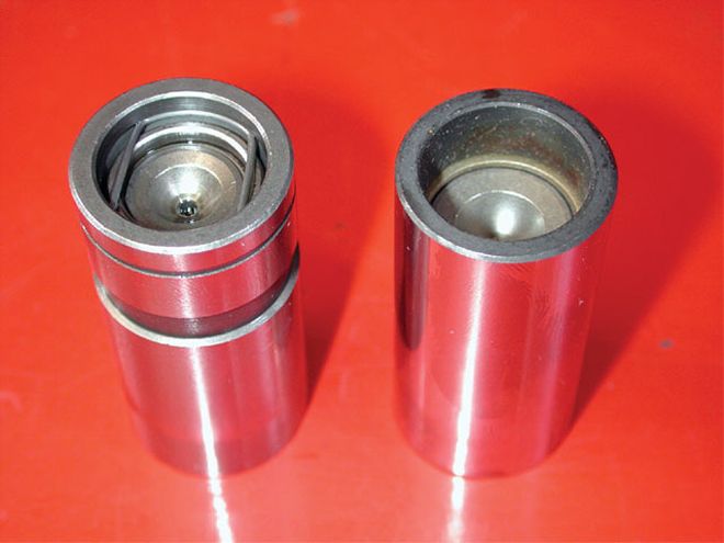 The pushrod seat in solid lifters (right) is deeper than those of hydraulics (left), so we ordered the correct length longer pushrods to compensate.
The Test
Testing a hydraulic versus solid isn't as simple as it may seem. While it may seem like just a matter of ordering solid- and hydraulic-lifter camshafts with the same specifications and running a test, there are a few considerations that are not apparent at first. Beginning with the advertised duration numbers, solids and hydraulics are rated by completely different standards. For instance, in the Competition Cams line, hydraulics are rated for duration at .008-inch lifter rise, while solids are typically rated at .020 inch.
Comparing a solid to a hydraulic by advertised duration is like comparing apples to oranges. In regard to lift, things are a little simpler. But again, a direct comparison of specs would be misleading. The lash needs to be subtracted from a solid cam's specs to arrive at the true lift at the valve, which can then be compared to the hydraulic cam's specs. Finally, we have duration at .050. While both types of cams are rated in the same way, for the duration at .050 spec, the numbers can't be directly compared. Duration at .050 is measured in crank degrees at .050-inch lifter rise on the opening and closing side of a lobe.
 We had checked both cams' installed centerline prior to the test, so on dyno day all we needed to do was line up the dots. Both were set to 106 degrees intake centerline.
The engine isn't interested in how far the lifter is moved, but rather only cares what is happening at the valves. With a solid, the lash will take up some of the lifter's motion before there is any valve motion. In fact, with the 1.6:1 rocker ratio in our test engine, the solid's duration at .050 reads as if the duration were taken at .0313-inch lifter rise as compared to hydraulic terms. That's a significant difference. A solid cam will behave like a hydraulic with approximately 10 degrees less duration at .050-inch lift.
All this makes it difficult to accurately match a solid- and hydraulic-lifter cam; matching the numbers in a cam catalog or on a spec card certainly can't do it. Our hydraulic cam was one of Comp's latest hydraulic profiles-an Xtreme Energy 275HL. These cams are ground with lobes specifically designed for high lift with a Mopar .904-inch tappet diameter. To match the fast rate of lift, we ordered a custom-ground solid cam based on Comp's MM-series .904 tappet-diameter lobe profiles. On the intake side, we went with the 6581 lobe, with a 6583 lobe chosen for the exhaust. The numbers on our solid cam seemed much larger in duration at .050, smaller in advertised duration, and very close on lift after compensating for lash. In fact, these two profiles were as close as we could approximate with the solid lobes available to us. We expected the idle vacuum and quality, cranking compression, and low-end output to be very similar between these two cams (see cam spec chart).
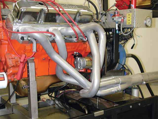
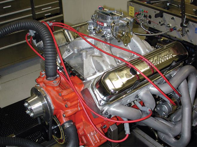
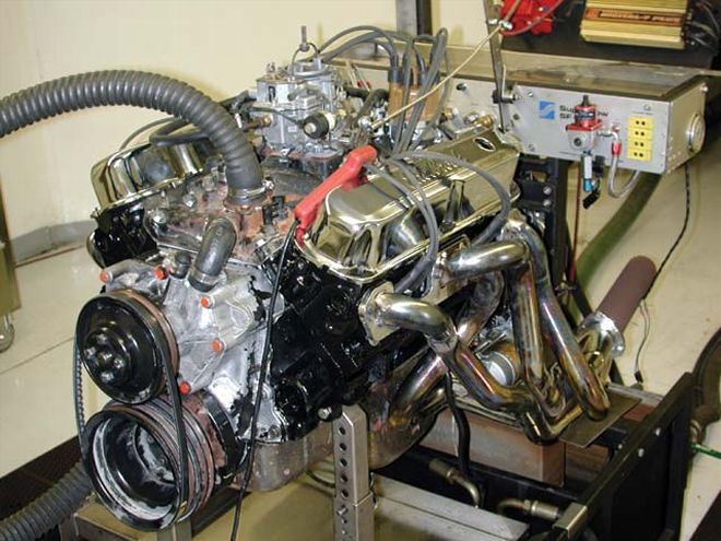
With cams and lifters in hand, we made the trip to Westech's dyno facilities for our little experiment. Our test engine was a 440 Chrysler wedge, actually measuring 446 ci after a .030-inch overbore, with a set of out-of-the-box Edelbrock heads, a Performer RPM intake, and 10.2:1 compression. For our baseline runs, we installed the Comp hydraulic XE275 camshaft and corresponding hydraulic lifters. The valvetrain included a set of 1.6:1 Comp Cams aluminum roller-rocker arms and pushrods. The engine combination was dialed in for timing and jetting on the dyno, with a Demon 950-cfm annular booster carb providing the air/fuel mix. The 440 idled with a lope at 900 rpm, and we recorded 12.7 inches Hg of vacuum.
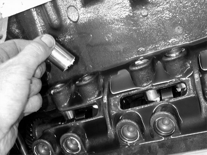 The solid lifters were given a coating of oil, a smear of cam grease on their base, and dropped into place.
With the engine warm, we spun it around to get a cranking compression reading. With the hydraulic camshaft, the 440 spun over with 180 psi-gauge pressure. Comparing the hydraulic cam's cranking compression and idle vacuum against the solid cam going in later will give a good indication of how closely we sized the two cams. All that was left to do were the power pulls to see how the hydraulic cam performed. The 440 ran strong, posting 520 hp at 5,400 rpm peak output, and 557 lb-ft of torque at 3,800 rpm. Looking at the curve, we could tell that output above 5,700 rpm was dropping off quickly-a characteristic of the onset of valvetrain control problems-even though there was no audible float. We had a hunch the solid would fare better as the rpm ramped up.
In short order, we opened the 440 for surgery, stripped it of the hydraulic stick, and stabbed in its place our custom-ground solid. We had the engine up and running again within an hour and fired it up for a cam break-in cycle for 15 minutes at 2,300 rpm. Settling the 440 back down to idle, we found the idle quality was as good as we had with the hydraulic. The dyno instruments read 12.6 inches of vacuum at the same 900-rpm engine speed used before, showing a virtually identical match. The engine was shut down to reset the valve lash hot, and we spun the engine for a cranking compression test. This time we had 178 psi, again a reading close to the hydraulic stick's values.
 The solid cam had our 440 boasting over 550 hp, and turned it into a high-rpm powerhouse at engine speeds where the hydraulic gave up. Dyno man Brule likes solids.
OK, the two cams idled about the same and made about the same vacuum level, but what about power through the rpm range? Our question was soon answered, as we read the results from the dyno monitor. The solid cranked 550 hp at 5,800 rpm, and 559 lb-ft of torque at 3,900. Interestingly, the torque levels were quite close at peak, and below at the low-to-middle of the rpm curve. At higher rpm-about 5,200 and above-the solid cam walked away from the hydraulic, pulling cleanly to 6,300 rpm, at which we limited our test. The solid cam's power curve was nicely shaped, exactly what we like to see.
We had a 30hp gain, with the same "size" camshaft, with the peak horsepower coming in a good 400 rpm higher. There was no part of the curve where the hydraulic showed a clear advantage. Seeing is believing-when it comes to spinning it up, a solid flat-tappet cam does have the edge.
Cam Chart XE275HLMM6581/6583Rated Duration275/287 DEG265/273 DEGDuration at .050"231/237 DEG239/247 DEGLobe Lift .350/.350" .358/.373"Gross Lift 1.6:1 Ratio .560/.560" .573/.597"Lift at Valve After Lash .560/.560" .555/.577"Lobe Separation Angle110 degree110 degreeInstalled Centerline106 degree106 degreeCranking psi Observed180 psi178 psiIdle Vacuum at {{{900}}} rpm12.712.6
Dyno Results
Tested At Westechsuperflow 901 Dyno
440 WedgeEngine TorqueRPMHYDSLD3000516515350054054538005575553900557559400055555745005495405000526521550049351359004144886000 4796300 437Engine HorsepowerRPMHYDSLD3000295294350036036340004234244500471462500050149654005205285500517537580049555059004655496000 5476300 525
Peak values are bold.