The first Great American Racing Series race ran successfully while this engine was still in the process of being built. This story is about that build. In this three-part series we will detail the preparation of the various parts, fitting the parts together, and making the final assembly and dyno’ing the motor. And at the end we will list all of the parts and manufacturers we used and a spec sheet showing all of the sizes and clearances for the build.
This is a street stock motor that fits the rules of Circle Track’s new Great American Racing Series and as such, may, or may not, be legal for your particular track or series. CT purposely left the rules a bit loose for the series in order to cover the wide range of rules packages throughout the region where the series takes place.
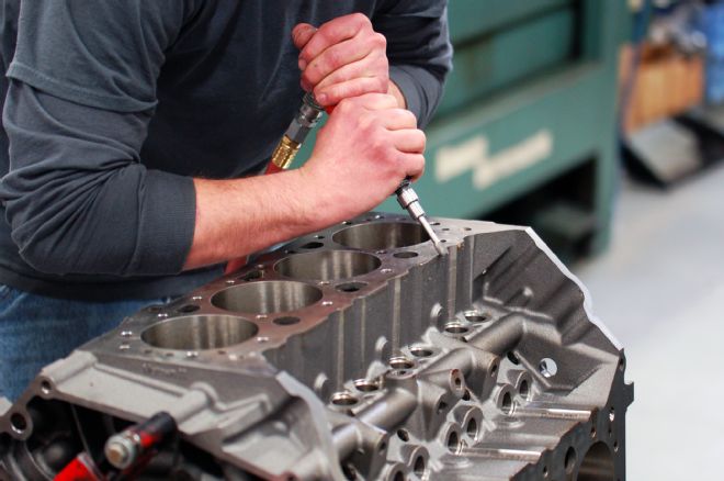 Before we begin our engine build, we needed to clean the block of all oil and other contaminants and debur all of the rough edges, oil passages, and oil drain backs, along the cylinder deck—front and rear—and along the area where the oil pan will be mounted. A high-speed Dremel tool or air tool will be perfect for this job.
 After the deburring process we needed to establish the deck height. We do this first to ensure the housing bores are parallel to the deck. These blocks can be used with a number of piston combinations and the builder can match the deck height to whatever piston and rod combination works best for the particular build.
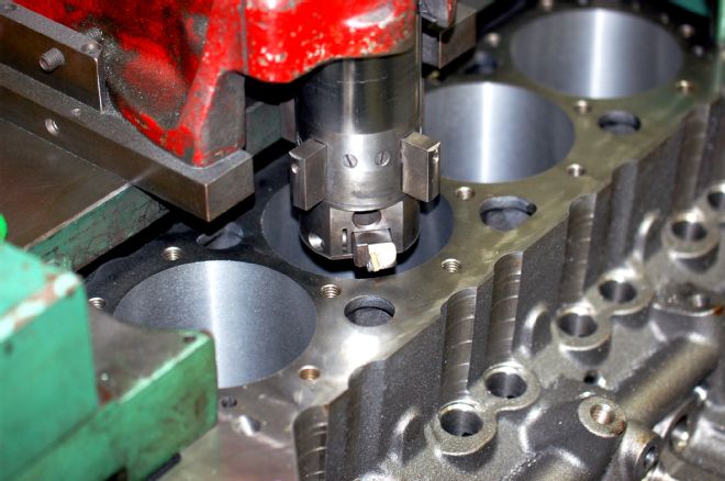 The World Products Motown block comes from the factory with a rough bore of 3.995. For this build we needed to bore the block to a rough bore of 4.025, we did this after establishing our deck height to ensure the bore was perpendicular to the deck.
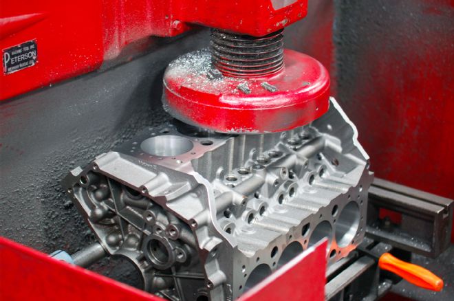 After completing the boring process it was time to finish hone the block to fit the Mahle pistons. Because this build called for cast-iron heads we installed the appropriate torque plate (cast iron, not aluminum) with the head gasket in place and the fasteners torqued to 75 lb-ft. We completed the operation setting the piston to wall clearance at 0.003 inch.
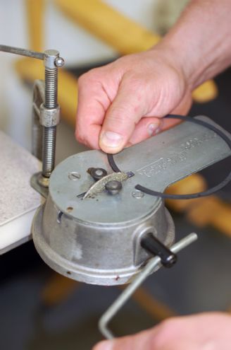
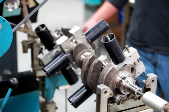 As a part of the initial checking process, we check the balance of the crank. We are using a Callies Compstar Ultra Light crank shaft in our G.A.R.S. motor and since we will be running some of the races on large tracks where we will see high rpm for sustained lengths of time, engine balance is critical to engine life. Later on we will weigh and match all of the rotating components, too.
Competitors in this series can run a stock motor right out of the “junk yard,” a crate motor right out of the crate, or run a build motor constructed by the team or an engine builder. The field is equalized by designating the weight of the car in relation to the power the team shows up with.
The motor build is being conducted by ISON Racing Engines out of Concord, Ohio, with lead builder Mike Hupertz and his team. They will be describing the build process and giving you, the reader, tips along the way that can help you understand what goes into having a motor built, or what you should know about building the motor, if you choose to tackle it yourself.
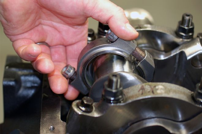
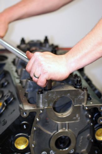 The next step in our build process is to check all of the main bearing bore sizes against our intended bearings; we install the bearings in the main caps then torque them to the manufacturer’s recommendations, and again check the bore against the crank journal sizes. We can mix and match over- and under size bearings to compensate for differences in clearance.
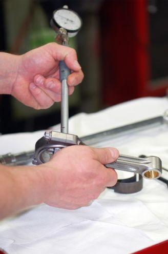
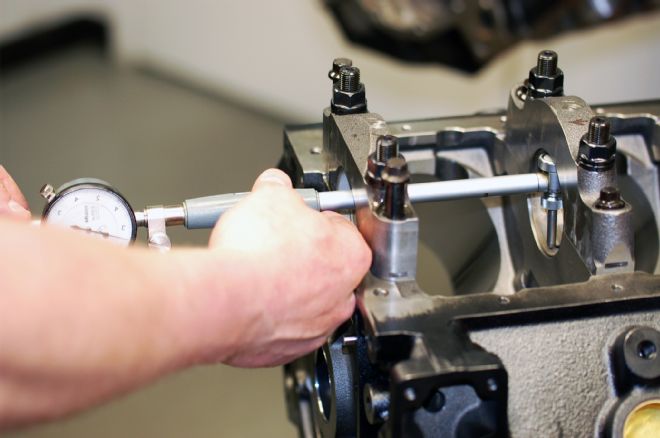 Here we are carefully measuring the bearing bore size at three places around each bore. We do this to ensure the bearing has the correct amount of vertical oil clearance as well the proper eccentricity. If you are building our own motor, take time to do this right because these clearances will largely determine the life of your motor.
 For hard-to-reach areas that need to be checked, the tool of choice is a dial bore, you want one that is graduated into ten thousands of an inch or 0.0001; the tool is set from gauge blocks or the appropriate size micrometer. These come in handy for any bore that you need to measure very accurately.
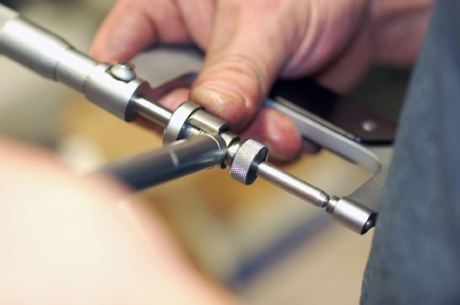
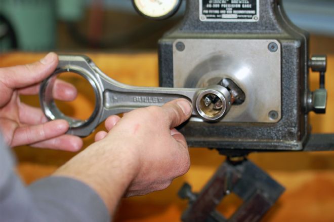
 Once we have sized the main bearing bores, we need to determine the rod bearing oil clearance. We again check the rod size with the bearing installed in three different places. We also check the wrist pin bore on the rod. This is a good time to number the rods as to the cylinder they will live within from now on. We are using six-inch Bullet Connecting Rod for a Small Block Chevy - 2.100 rod Journal 7/16 bolt (PN# BC21-60071) from CP-Carillo.
 Once we have determined the connecting rod crank size and wrist pin bore, we measure the wrist pins themselves.
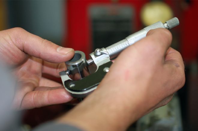
 To match the wrist pin diameter to the rod bore, we carefully resize the bore for a perfect fit of 0.0005.
This build is designed to demonstrate what can be done to create a motor that is versatile and that will live a long life being run on both dirt and asphalt, short and longer tracks, and having the durability to stand driving the wheels off the car. What you choose for your engine can encompass many different combinations of parts and a variety of cost levels. The durability may be greater with the higher priced parts, but the power level will be similar between levels of motors.
In the G.A.R.S. series, the engines are restricted to using a Holly 4412 2 bbl, 500-cfm carburetor. You could go as radical as you want with cam designs (all cams are limited to 0.550-inch maximum lift), heads, valves, and so on, but you will only flow 500 cfm, so some money could be wasted on parts designed for much higher rpm than what these motors will effectively run at and produce usable horsepower.
Other rules of importance for the G.A.R.S. series include limiting the engines to 364 ci, unless you have a larger motor up to 410 ci, and then you must run 100 pounds more weight.
The carburetor is the Holly 4412 as we stated and the intake must be cast iron or the aluminum Victor Jr. from Edelbrock. The maximum height from the floor to the bottom of the carburetor is 4.25 inches.
The heads must be cast-iron 23-degree heads, OEM or aftermarket, brands and part numbers specified, and the valves must be steel or stainless steel and retain the stock valve stem sizing. Stamped steel rockers or rollers may be used, but no shaft rockers and the cost must be at or under $200 retail value. The maximum valvespring seat pressure is 150 pounds.
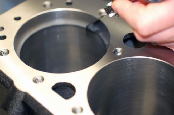
 We now need to check the piston ring gaps. We use a ring squaring tool for this but if one is not available to you, an alternative method would be to use a flat-top piston. This will do the same thing. You want to ensure that the ring is square in the bore and sits evenly to the deck, roughly 1 inch down is the proper depth.
 For our build we used the rings supplied with the Mahle pistons, these are 1.5/1.5/3mm, which are a file fit type. For a race engine, the file fit rings let you put the ring gaps at the desired size for a wide range of applications. We filed the rings to a top gap of 0.021 and a second gap 0.025 for this build, if you’re unsure of the proper gaps, error on the larger side rather than the smaller side, you may lose a little horsepower but the rings won’t butt causing extensive engine damage. Be sure to deburr the ring after the filing process so it sits properly in the ring land.
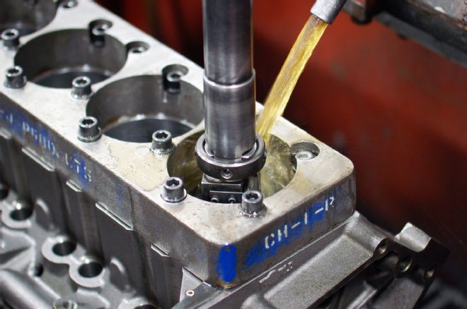
 The same lubrication process takes place with all bearing surfaces. Here we use an assembly lubricant that will allow the engine to live and be properly lubricated until the oil is efficiently flowing through the motor on the first startup.
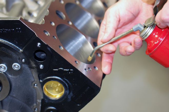
 Before placing anything in the cylinders, we always lubricate the bores with the proper break-in oil. There are several manufacturers that offer specific engine oil with the correct additive package for proper break-in.
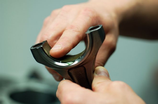
 When installing your rods and pistons, be very careful with the edges of the rods and caps. There are sharp edges that can scratch and gall the crank or cylinder surfaces.
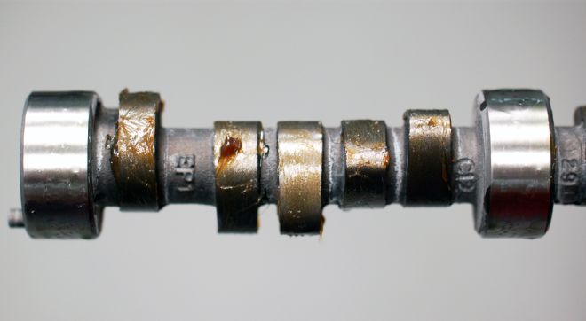 Before installing the cam, we coat the lobes with a high-quality lubricant that promotes the proper layer of protection to ensure there will be no troubles during the break-in process; you want to make sure you have good coverage, especially on the nose of the camshaft as this is where the highest spring pressures will be. This lubricant is made to dissolve into the break-in oil and stay in contact with the lobes long enough for the engine oil to completely coat all of the parts when the motor is first fired up.
Stock or aftermarket cast-iron blocks must be used and they must retain a stock appearance and must not be lightened. Only timing chains are allowed and you can use solid or hydraulic lifters, but no roller cams. The maximum lift for the cam is 0.550 inch.
The oil pan must be steel and you can use an oil cooler, but no dry sump, wet sump only. To supply fuel, you must use a stock-type fuel pump, no electric fuel pumps allowed. The exhaust manifold can be stock OEM, or mild steel headers (2½-inch diameter only), with a Schoenfeld muffler, PN 83030 for mandatory use with headers. The sound level maximum for all cars is 95 dB or less.
So there you go, simple but effective rules that are loose enough to include many different rules packages whereby the tech committee for G.A.R.S. will evaluate the equalizing of the field as the series progresses and as necessary. We want tight and competitive racing where the driving, setup, and the preparation is what determines the success of the team. On to the build!
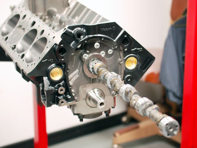
 The insertion of the cam is another process that should be done carefully to ensure that none of the cam lobes are scratched. Take your time and keep rotating the cam as it goes in to check for any binding or tightness.
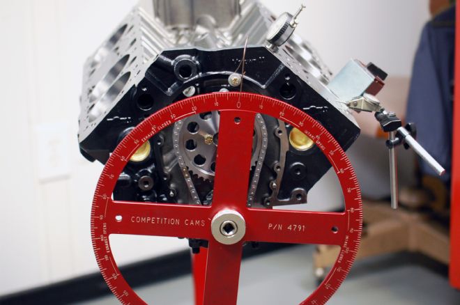
 Once the cam is installed, we also install the number one piston and timing chain. We then mount a degree wheel onto the crank. The larger the degree wheel is the more accurate the process will be. This process is in preparation for degreeing the cam against top dead center of the number one piston.
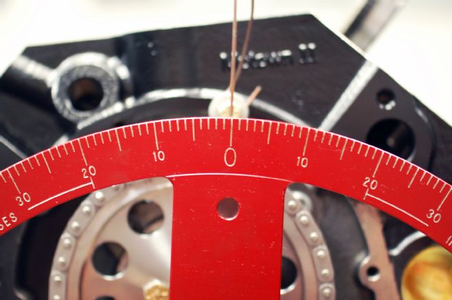
 To find top dead center of the number one piston, we simply use a magnetic base with an indicator positioned over the number one piston (Chevy is on the driver side front cylinder), we then rotate the crank until the indicator reads the highest reading, ensuring that the piston is at its highest point or TDC. We then position the pointer to zero on the degree wheel.