
Consider this: Engines don't burn just fuel, they burn fuel and air. The more air, the more power, and fuel delivery is adjusted accordingly...or so the axiom goes. In reality, air quantity must be equated with air quality, for without proper conditioning of mixtures, combustion efficiency will suffer. More air isn't always more power...as you will soon discover.
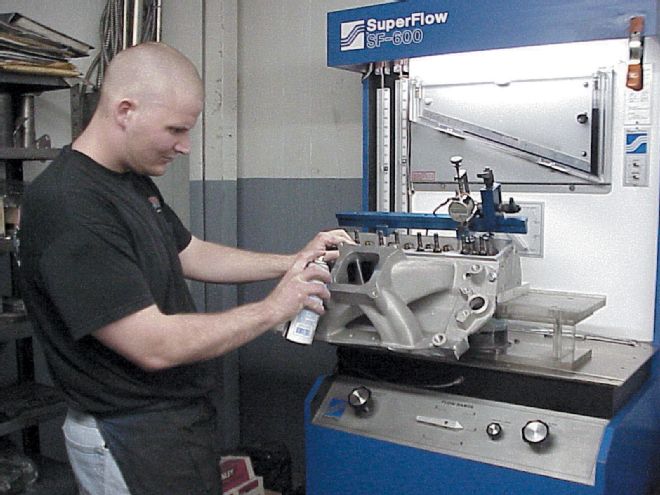 A simple dye spray may be enough to unlock more power in a racing engine.
Some Fundamental Considerations
Let's say you have an engine that produces a given level of power, demonstrates certain brake specific fuel consumption (BSFC), and requires a known quantity of spark timing. Further, assume this engine to be our "baseline" for discussion. As you might assume, these conditions are produced with what we'll also call "baseline combustion efficiency."
Now, without changing net airflow into the engine, suppose we perform a set of modifications intended only to improve mixture quality (homogeneity). In conventional terms, this simply means keeping more fuel in suspension prior to and during combustion. We want to emphasize that net fuel and airflow are not changed, only mixture quality.
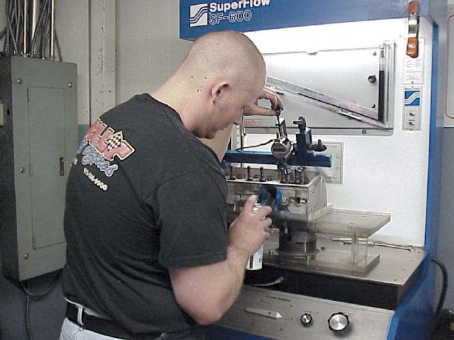 Short bursts of aerosol machinist dye work well to establish airflow patterns. Excessive use can mask the contrast of how the dye represents the intensity of where separated fuel will migrate. Before concluding inlet port and chamber designs, effects of the intake manifold should be determined. While this does not include the influence of a carburetor, it does reveal the impact of ports and runners working together. Note proximity of can to entry, as demonstrated by Wells Racing's Ricky Stapleton.
From these types of modifications, some interesting results can occur. First, improved mixing (homogenization) tends to reduce fuel particle size. The smaller their size, the faster the burn, generally speaking. Then, as stated in previous technical materials in Circle Track, cylinder pressure rises more quickly, enabling slight reductions in total ignition spark timing. As either or both of these conditions develop, net torque on the crankshaft increases, largely by the reduction in negative work (pressure on the piston during combustion and prior to TDC compression position) and a quicker burn.
These conditions trace directly to improved mixture quality, which then becomes the enabler for torque increases. More to the point, it is the "construction" of improved air quality that supports more efficient fuel atomization and burn efficiency gains.
The Problem of Air/Fuel Separation
This is a classical problem when changing the direction or flow rate (or both) of fuel-suspended airflow. The relative differences in compressibility and weight (by volume) of air and fuel leads to their departure during changes in energy state (flow direction, rate, or both). It is the condition of the air that tends to affect how fuel is delivered. As an analogy, the air steam could be equated to a flowing river and fuel likened to leaves thrown into the stream. The motion of the river stream significantly affects the direction and movement of the leaves. By affecting the characteristics of the stream, movement of the leaves can be directed. Such is the case when transmitting fuel particles through an engine's intake track.
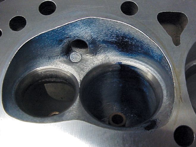
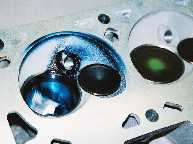 In this LS1 chamber, note the wash of fuel against the bowl area and across the spark plug boss. While this direction of mixture motion toward the exhaust side of the chamber is desirable, the heavy concentration of dye beneath the valve seat and absence around the backside of the chamber wall is not.
Interestingly, many cylinder head modifiers spend inordinate amounts of time sorting out port designs, valve seat and bowl dimensions, and combustion chamber shapes to optimize net airflow. Not to diminish the value of this approach to increasing an engine's output, especially if fuel is admitted up-stream of the combustion space, but omission of how such airflow affects the delivery of fuel can lead to an imbalance between increased air and power. Initially, the idea of using some form of atomized spray that would leave its mark on flow surfaces was conceived to address the air/fuel separation problem.
In time, as the windows of information about this approach began to open, it became evident that other aspects of improving combustion efficiency could be explored. In fact, this sequence of investigation led to the notion of using kinetic energy already contained in the inlet air stream to aid re-suspension of separated fuel by the method of dimpling or a comparable approach to surface imperfections. There are, of course, more sophisticated methods to study active flow and the influence of variables that affect its behavior and characteristics. However, most of you don't have access to CFD (Computational Fluid Dynamics) or comparable techniques. So at the more grassroots level, the approach described in this story is worthwhile.
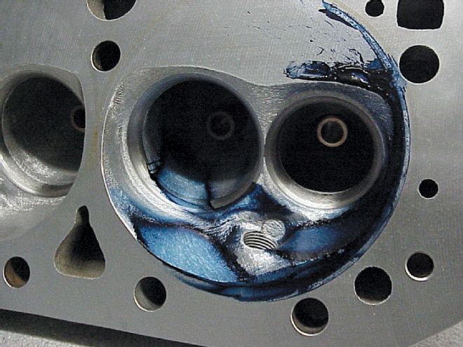 While canting the back wall of this combustion chamber may have improved raw airflow (as measured on a bench), note the concentration of fuel wash and lack of movement in the area of the spark plug nose. Rotation of the flow in a counter-clockwise direction (shown) is favorable, but the collection of raw fuel just past the exhaust valve pocket is not. Matching such patterns with piston crown shapes and surface texture is important to boosting combustion efficiency.
One of the purposes of this story is to reveal the process of using both dye traces and flow path surface roughness to aid fuel atomization and suspension in the air stream. Although considered by some engine builders to be a "crutch" or "band-aid" to resolving a problem inherent in virtually any internal combustion engine, the latter of these two methods is proven, recognized by the U.S. Patent office as viable intellectual property, and increasingly practiced wide-scale by builders of several types of engines. As previously stated, it is not "snake oil" and is worthy of the time taken to understand and practice, at least in the opinion of this writer.
In the Real World of Making Power...
Dennis Wells of Wells Racing Engines shared comments about his experience with the airflow/dye method of flow analysis.
 This is good. Note uniformity of pattern that includes activity in proximity of the spark plug nose and lack of "fuel" buildup both against the chamber's back wall and sidewall of the exhaust valve pocket. Uniformity of pattern suggests a narrow range of air/fuel ratios will be present in the combustion space, as opposed to a wider range of ratios when patterns indicate sharper contrast of dye residue.
"Before I began practicing this method, we'd tear down an engine, look at the burn patterns on piston tops and combustion chambers and wonder about what we saw. Sometimes, we'd see no residue; other times, we'd see varying shades of carbon buildup. Even though it occurred to us these patterns were probably an indication of something we should understand, we really didn't.
"Then, I was introduced to using a spray-type dye during airflow bench testing of cylinder heads. By studying areas where the dye was really concentrated, it appeared these locations indicated fuel wash or separation from the airflow. What really got my attention was when we started changing the surface texture of these areas and began to see power increases with little or no changes in total air or fuel flow. Exhaust gas temperatures also began to drop, suggesting the burn was taking place faster and that more of the fuel already in the combustion chamber was now being burned. We also discovered less spark timing was required for best power," Wells said.
"As I've used this method of airflow study, we've found other areas for modifications that help increase horsepower. One of these has been in working with two-plane manifolds and the use of carburetor spacers. I never realized why spacers seemed to make more power until we did some dye work and discovered the problem of fuel separating on the manifold's upper floor. We discovered that as the carburetor is raised, this separation problem was reduced and more power was produced from about the same amount of fuel and air we used before adding the spacer. In some cases, we found it was possible to lean down the carburetor and make even more power. Sometimes this wasn't necessary because raising the carburetor also tends to reduce fuel-metering signal and makes the engine leaner, anyway.
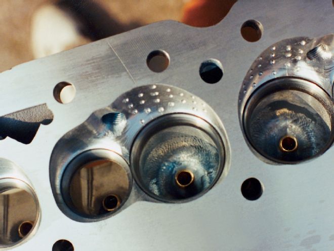 In areas where fuel is impacting combustion surfaces and "washing" into rich air/fuel ratio development, surfaces can be dimpled to create eddies or boundary layer activity intended to restore separated fuel into the air stream. While this approach may be considered a "band-aid" method, it can be highly effective, cost-effective, and power producing.
"Overall, there are several things (construction techniques) we've found helpful using the dye method," Wells continued. "One is that it points to where flow surface texture changes will help. We like to use dimples in these areas because they tend to put separated fuel back into the air stream. What this does is allow otherwise wasted fuel to be burned. This is power, any way you look at it. We also discovered that how air is delivered to the combustion chamber, when measuring flow patterns with a head alone, usually changes when you bolt on the intake manifold. So just studying these patterns with the effects of the manifold can be misleading. We've worked on optimizing flow patterns in the combustion chamber and discovered all this changes when the manifold is installed.
"What's really interesting is that we've used this method to identify areas of fuel separation, created dimple patterns, and found power gains without any significant changes in the amount of air flowed. Plus, we've also discovered that what we'd previously thought were helpful modifications in an intake manifold that increased air flow actually caused separation problems downstream. The bottom line of this was we didn't see power gains that the increased airflow indicated we should, which was the result of mixture quality problems we'd created by just going for more air. The old story about 'more air isn't always more power' is true in a lot of cases where these gains upset combustion efficiency.
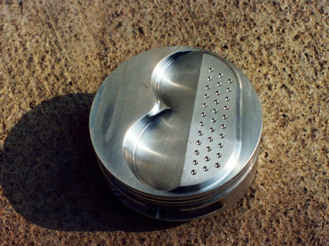 As a companion to textured combustion chamber surfaces, the combustion chamber "floor" piston crowns should be configured to further aid mixture quality, both prior to and during the burn. Location and arrangement of dimples is a function of burn and/or dye patterns, as outlined in the story.
"I guess if I had to summarize all this is, I would say you can use an airflow bench for more than just measuring total flow," said Wells. "At first, it may be difficult to understand how to read the patterns the dye method produces. But by comparing them to existing combustion patterns you can see on piston crowns and combustion chambers, it's possible to figure out what needs to be done to improve combustion efficiency and power. Especially if you use dimples in areas where fuel is separating and collecting on these surfaces, the dye will show you the areas where the dimples should go. Even if you don't use dimples, these patterns will give a picture of what's changing when modifications are made to intake manifold runners, plenum chambers, intake ports, and combustion chambers. In fact, just about anything that affects the quality of air delivered to the combustion space can be included by this method."