In nearly 40 years of continuous Mustang Monthly publishing we’ve seen countless full-scale restorations that just don’t work the way they should. They look great, but they just don’t operate as Ford originally intended. And that’s because too many of us wing it while troubleshooting and trying to fix our Mustangs instead of getting right down to proper function and fix. We “fix” it but just can’t get it working properly, so we just leave it the way it is and find a way to live with it.
We’ve talked about the refrigeration side of air conditioning before. We’ve also explained engine cooling system function and how it provides warmth to your Mustang’s interior in winter. However, there’s more to your Mustang’s climate control than just hot and cold air. It is also about how hot and cold air are managed and controlled along with dehumidification. No one wants cold air on their feet in winter, nor do they want hot air on their face in summer. What’s more, you want cool, dry, conditioned air when humidity goes skyward.
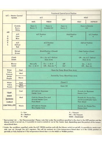
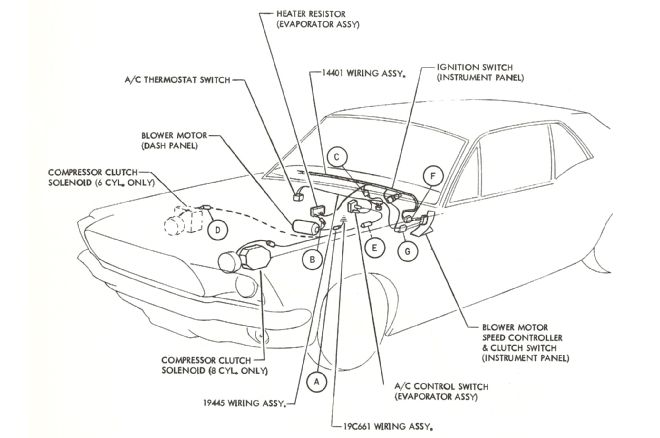
Your Mustang’s SelectAire (in dash) system is electrical, vacuum, engine coolant, and refrigeration. Electrical and vacuum are how SelectAire is controlled; hot engine coolant provides the heat; and refrigeration provides the cold. How these elements go to work depends on how engine intake manifold vacuum is routed by the SelectAire control valve located in your climate control panel. Let’s take an in-depth look at how that works so you’ll know how to fix the system when something stops working.
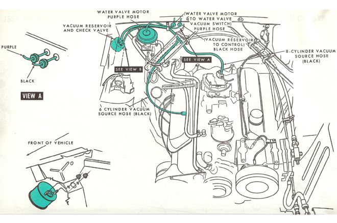
1. Here’s a simple schematic illustrating how the 1967-1978 Mustang climate control vacuum system works. We’re using the engine’s intake manifold vacuum (suction) to do our work for us. Vacuum is used to operate air doors and the hot water valve in your Mustang’s SelectAire system. When you move these controls, you will hear vacuum (hissing) being directed to door servo motors and the hot water valve.
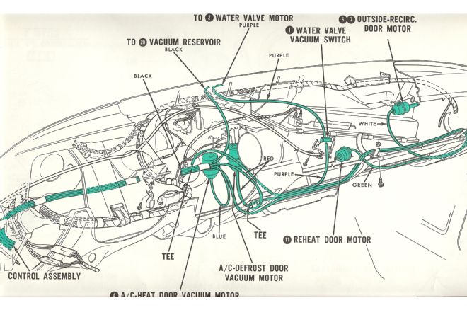
2. This is the 1967-1968 vacuum line harness system of proper routing from door to door. Originally this harness was bundled for easy assembly line installation. You may do the same thing in your restoration efforts following the same path.
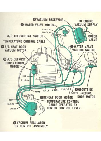
3. Electrical and vacuum functions are illustrated here. When you apply heat, you are moving the Bowden cable, which affects the heat control door and hot water valve function. The hot water valve is either on or off depending upon vacuum application. Each vacuum port at the vacuum regulator directs vacuum to the appropriate servo motor depending upon control position.
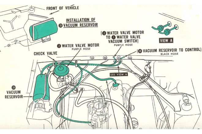
4. Vacuum originates at the engine’s intake manifold and is applied first to a vacuum reservoir, which maintains vacuum. A check valve between the reservoir and vacuum regulator control helps the system maintain steady vacuum.
5. Manifold vacuum begins here at the intake manifold. This is a 289/302 manifold fitting, which accommodates power brakes, automatic transmission vacuum modulator, and SelectAire vacuum.
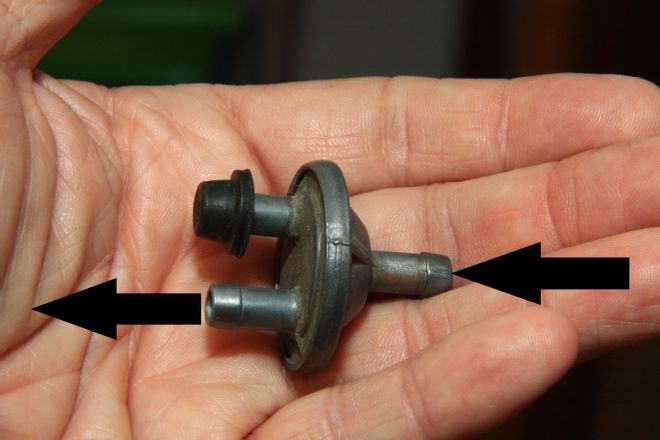
6. Intake manifold vacuum reaches this check valve, which allows vacuum one way but not the other. Intake manifold vacuum is drawn toward the engine, yet isn’t allowed to escape from the vacuum reservoir back to the engine. When you shut the engine off, vacuum is maintained thanks to this valve. This particular check valve has two receiver ports instead of the more common single port. One is capped.
7. This close-up of the vacuum check valve demonstrates vacuum flow in one direction only. If you blow through the beveled side of this valve, no air will flow. If you blow through the flat side, you get airflow. The engine pulls air from the beveled side, yet vacuum cannot escape from the reservoir back to the engine.
8. For 1968-1970, Ford went to a vacuum reservoir in the right rear inner fender with an integral vacuum check valve, as shown in this 1968 illustration.
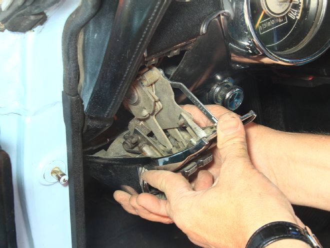
9. The vacuum regulator located on the control assembly vectors vacuum to each of the servo motors and the hot water valve. Scott Drake’s vacuum hose kit from National Parts Depot is color coded with precut hoses, so it’s easy to install. Follow the schematic in this article and you can’t possibly mess this up.
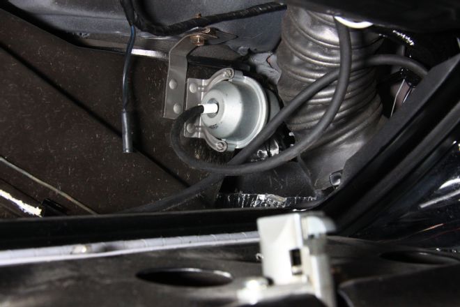
10. The sliding “heat” control performs two functions. It controls vacuum to the hot water valve and regulates the heat control air door. When the sliding control leaves the “at rest” position, vacuum is immediately applied to the hot water valve allowing coolant flow through the heater core. At the same time, the heat control door allows or limits hot air flow through the heater core and box. This is the hot water vacuum control valve, which is either on or off.
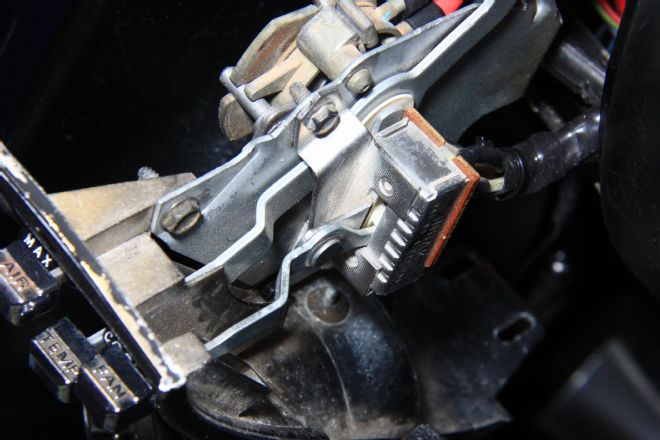
11. Underneath the dashboard is a better look at the hot water control valve and heat control door. When the heat slider is completely off, the hot water valve is closed and so is the heat door. On the bottom is the reheat door servo motor.
12. This is the outside air/recirculation door servo motor, which opens the door to recirculate interior air and closes to bring in outside air. When you move the selector from “AC” to “MAX,” this door opens and you’re recirculating cabin air. It also becomes louder.
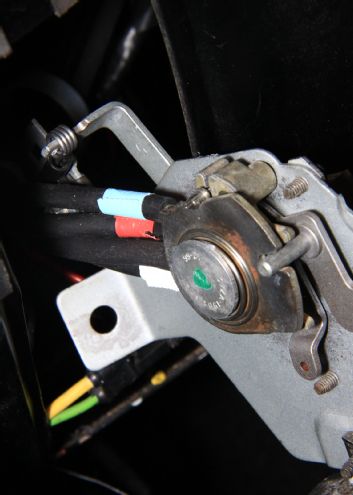
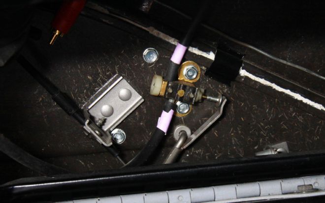
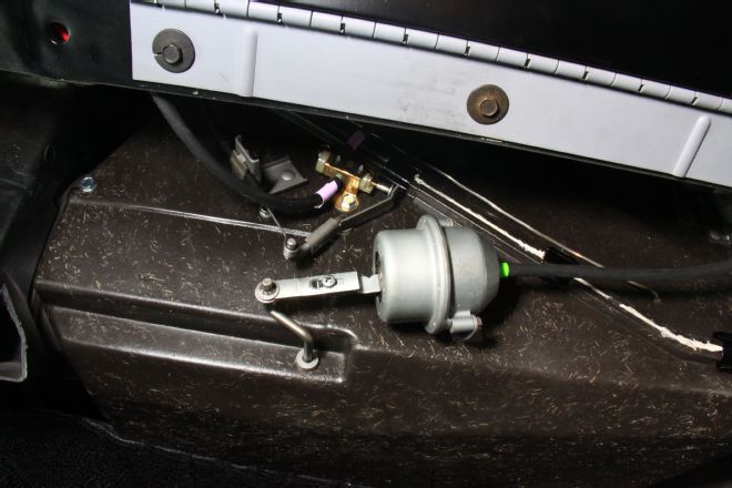
13. Here are where vacuum and electrical control work together. This is the air conditioning compressor’s primary switch, which is closed when the A/C-heat servo motor moves the door from heat to air conditioning (air vectored to dashboard vents). This switch closes, providing the first segment of compressor clutch power.
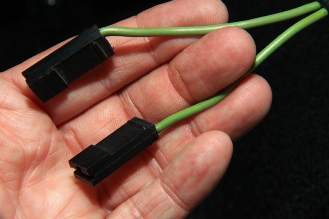
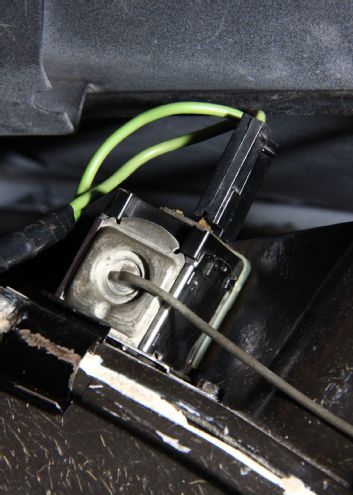
14. When you see green wires, you have compressor clutch power in your hands. The first phase of compressor clutch power is at the A/C compressor switch just mentioned. But wait, there’s more. Power flows next to the compressor thermostatic switch, which opens and closes based on evaporator temperature. If this switch is open, you will not get compressor clutch engagement.
What’s This Thing Do?
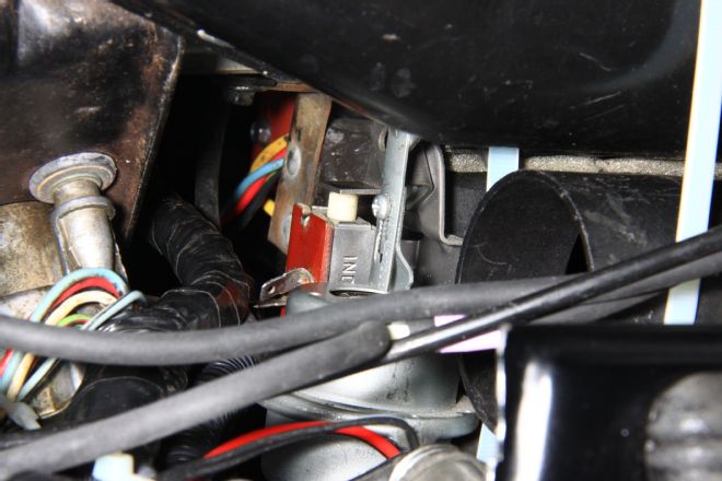
This is the thermostatic control switch located on the air handler under your Mustang’s dashboard. This switch is temperature modulated based on how cold the evaporator is. A thermocouple (capillary tube) runs from the switch to the evaporator. Inside the capillary tube is refrigerant in a vacuum. Expansion and contraction of refrigerant against diaphragm spring pressure controls switch function. The colder the evaporator the less the refrigerant pressure (switch open). By the same token, the warmer the evaporator the greater the refrigerant pressure (switch closed).
When evaporator temperature reaches a given value (cold) the switch opens, disengaging the compressor clutch. As the evaporator warms, pressure increases in the capillary tube, closing the switch and engaging the compressor clutch. Most thermostatic compressor switches are adjustable, enabling you to control cabin temperature. If the compressor ran all the time your evaporator would freeze up, hence the need for control.
If you experience the absence of compressor function it is mostly likely the thermostatic control switch, which is easy to replace. To determine thermostatic switch integrity, simply bypass the switch with a jumper. If the compressor clutch engages, replace the switch. If it still doesn’t engage, check the compressor switch at the A/C-heat vacuum servo motor. Simply bypass both switches to ascertain compressor function. If the compressor clutch does not engage make sure you have power to the compressor clutch. If you have power at the compressor clutch, service or replace the clutch.
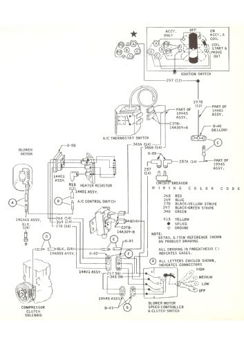
15. This electrical diagram illustrates the basics of your 1967-1978 SelectAire system. Before you is a very simple electrical subsystem. Power comes from two sources: an external 25-amp circuit breaker for the compressor clutch and a 14-amp fuse for the blower. Completion of each circuit happens when we complete the circuit to ground via a switch. Blower power to ground is via the variable resistor in the plenum. Compressor power grounds via the magnetic clutch.
16. The fan switch is a three-position switch. However, it is not a variable resistor so it does not directly control fan speed. It channels power to the blower motor via a three-position variable resistor at the blower.
Heater Only
We’re going to touch briefly on heater/defroster only to offer insight into how a basic Mustang heater functions. The standard Mustang heater consists of a fan switch, variable resistor, and cable-operated air doors. Airflow generated by the blower is vectored to the floor for heat or up to the defroster outlets.
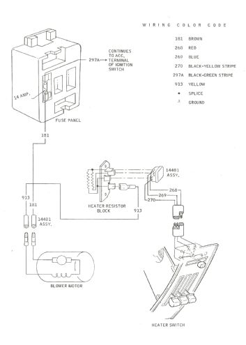 The heater’s electrical system consists of a three-position fan switch located at the controller and a variable resistor positioned in the heater box. The variable resistor is the same one used with SelectAire climate control. Each level of resistance controls current flow to ground, which determines blower speed. The blower circuit is protected by a 14-amp fuse located in the fuse box.